

Cliff7600
-
Content count
1,162 -
Joined
-
Last visited
-
Days Won
11
Posts posted by Cliff7600
-
-
It's the pilot increasing the heating system while the exterior get colder.
During the battle of Guadalcanal, B-17 crews had to live by +50 deg Celsius / 120 deg F on the ground and fly by -50 deg C / -60 deg F at altitude. Hard for men and machines.
(If I remember right)And on the other hand it's a cockpit entry that should work for an engine.
I use it on other planes to have the exterior temperature.-----------------------------

-
1 hour ago, sophocles said:is it supposed to move?
Yes and no, I did half the job.
Have you ever saw an european guy trying to set temperature with an US device ?
[CabinTemp]
Type=INLET_TEMPERATURE_INDICATOR
NodeName=Selector_dial_ base_01
MovementType=ROTATION_Z
Set[01].Position=140.0
Set[01].Value=-56.0
Set[02].Position=-140.0
Set[02].Value=30.0"Set[02] value" to 30 or more as you like (Celsius lol )
Me, climbing to 30000 ft to check the temperature setting...
Also I use the mesh name "Selector_dial_ base_01" not "Selector_dial_base_01", just in case you have deleted the space just before "base" in the LOD file.
-
 1
1
-
-
Hello and welcome !
See post below, what Wrench said.
----------------------------------------------------------------------------------------
The problem comes from the terrain used.
GermanyCE is the stock terrain by default and the problem won't happen as long as you stay between 1948 and 1984 (or maybe earlier/later).To solve it you should extract the "GermanyCE.ini" file and add the entry :
[AllowedDates]
StartDate=1923
EndDate=2030With the years you want to have.
But before doing such I would recommand to download a terrain and see how it's done.
When you understood how things work then go modify it, but in the meanwhile take your time and don't try anything not under control xDHere you will find some content to read :
https://combatace.com/forums/forum/268-thirdwire-strike-fighters-2-series-knowledge-base/
It won't adress all your issues but it's the place where to start.
-----------------------------------
"Plane Year Problem" is better than "PLANE YEAR PROBLEM"
-
I have a very little contribution to add to the cockpit.ini :
Instrument[xxx]=CabinTemp
[CabinTemp]
Type=INLET_TEMPERATURE_INDICATOR
NodeName=Selector_dial_ base_01
MovementType=ROTATION_Z
Set[01].Position=140.0
Set[01].Value=-56.0
Set[02].Position=-140.0
Set[02].Value=0.0It adds nothing, but it works

Great model !!!
------------------------------- Edit --------------------------------------
Set[02].Value=30 or more
-
Hey ! Someone left a wreck under this net
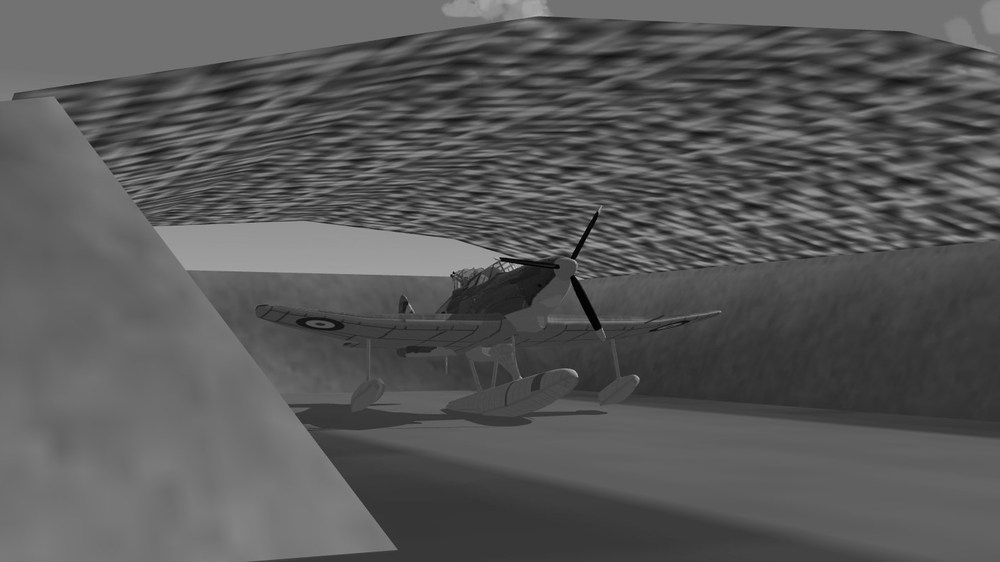
---------------------------------------------- Few years earlier -------------------------------------------------------------------------------------------------------------

And in case you wonder... yes it floats. Though a bit heavy for the float of the Rufe.
Double "What-if", never happened either in real life or in game (officially...)

-
8
-
 1
1
-
-
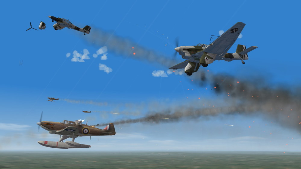
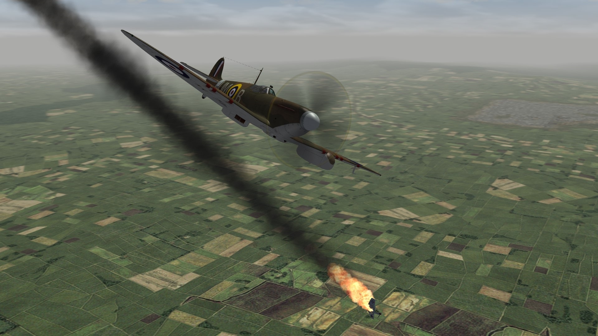
Nordo, Armed and Unafraid

Made it ! I knew it
Next time I'll take the cameras

-
4
-
-
Hi
In the "decals.ini" file, in each skin folder when decals are used, there' s a difference between :
DecalLevel=2
the decal is linked by its name in the decal folder to one aircraft by the "numbers" file, numbered from 000 to n-1 (000 to 025 if 26 numbers in total), no matter how many kills you have.
and :
DecalLevel=3
that will activate the kill decal corresponding to the aerial victory number recorded in the pilot.plt file, and will be shown on every aircraft selected in game by the player as long as there's is a proper "DecalLevel=3" part in the decals.ini file.
DecalLevel=0 decal always displayed
DecalLevel=1 linked to the squadron.ini list and decals must be named consequently. -
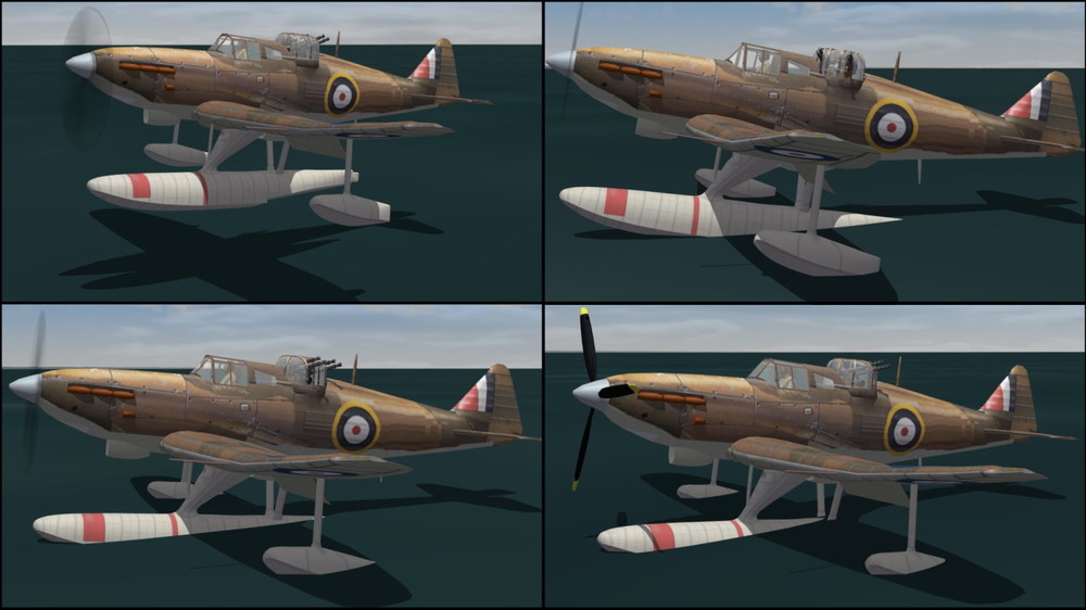
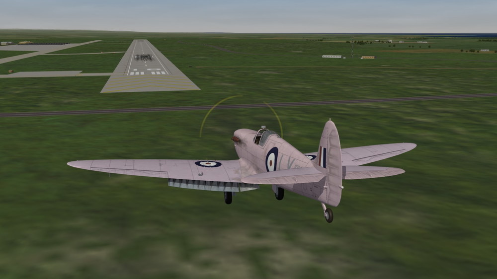
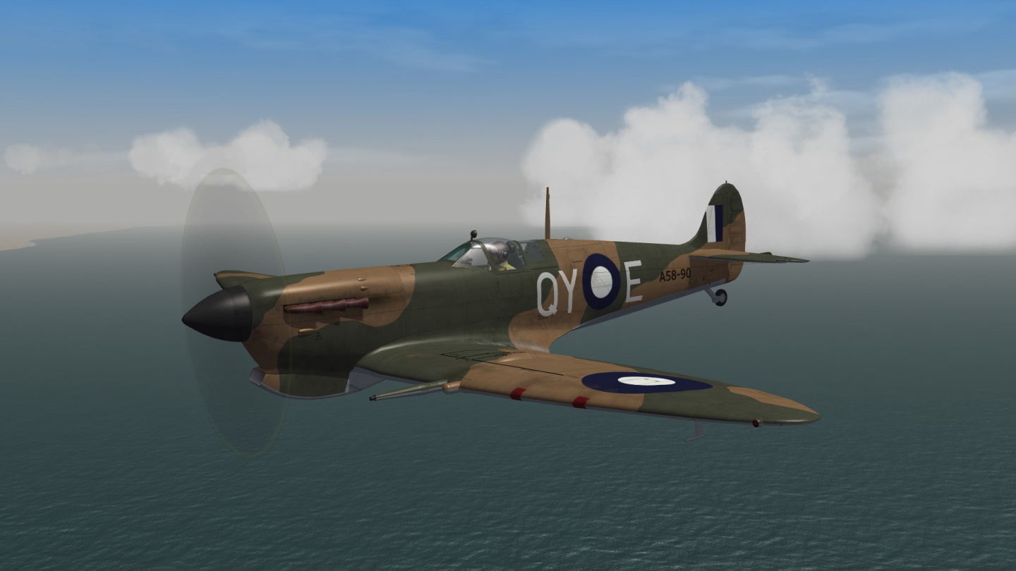
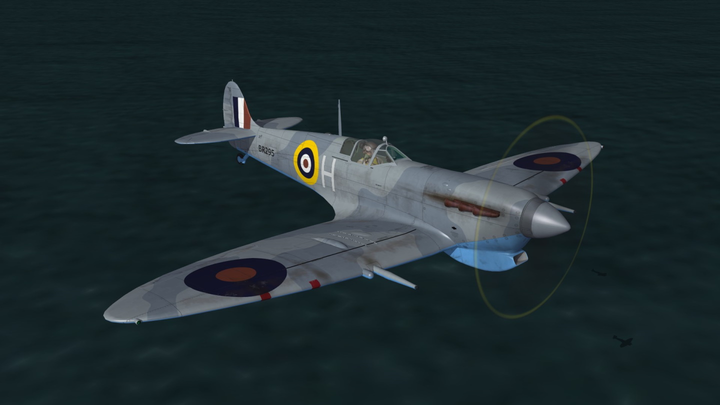
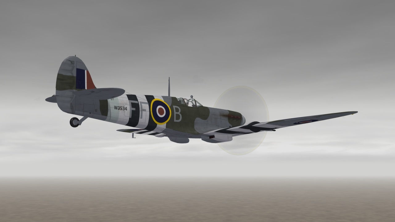
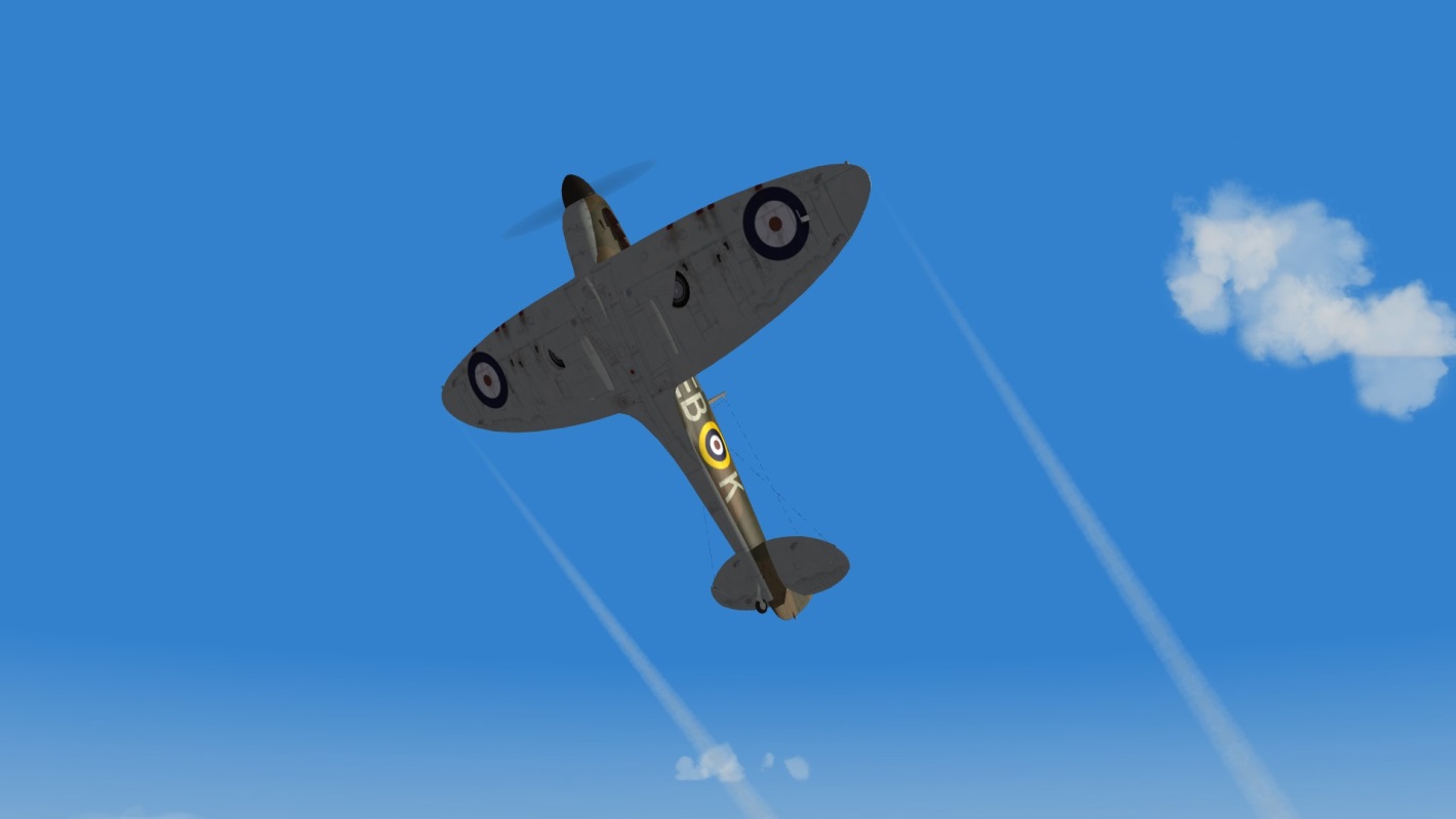
Painted in Great Britain
Re-painted in Australia
and again

Re-painted on a british carrier
Re-painted on a US Navy carrier
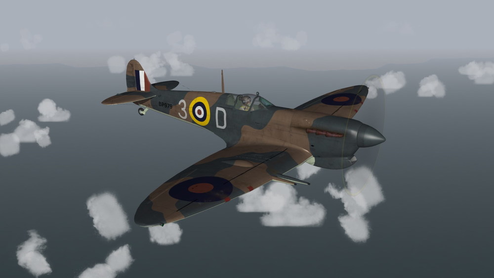
Re-painted in Malta
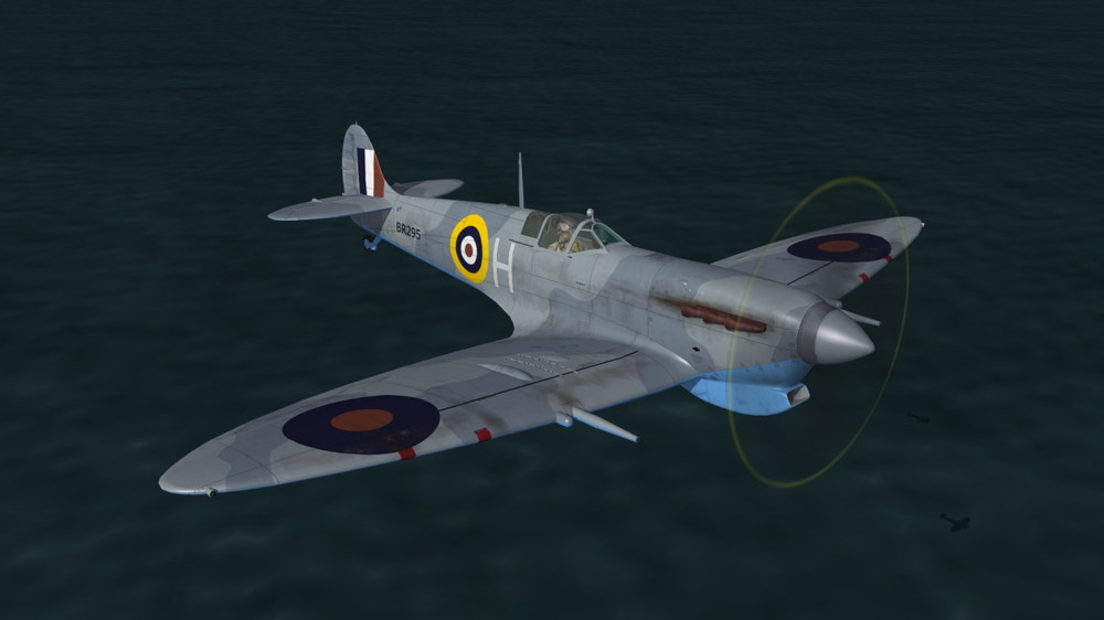
So far 17 aircrafts, (around) 36 skins and still rolling !
Kudos to Logan4 !
-
7
-
 1
1
-
-
-
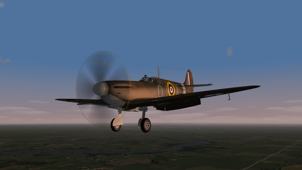
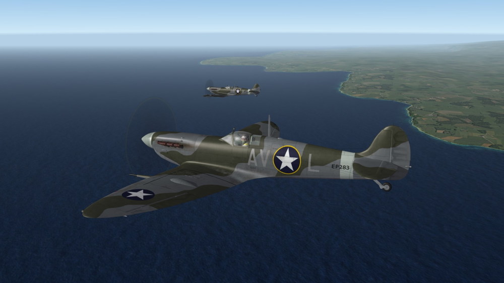
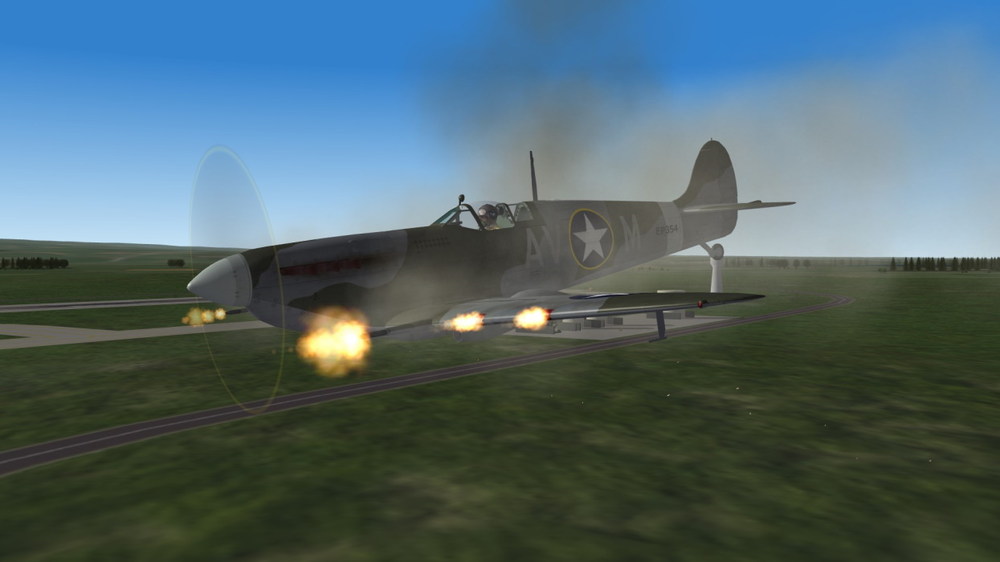
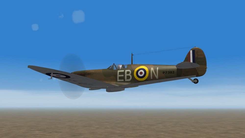
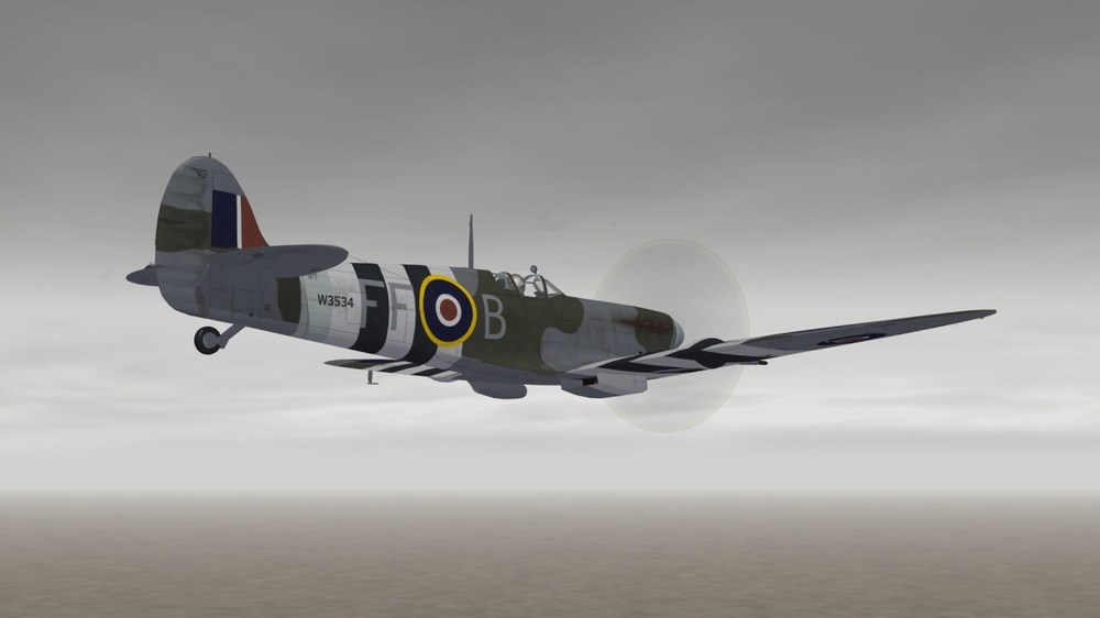
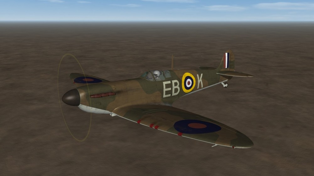
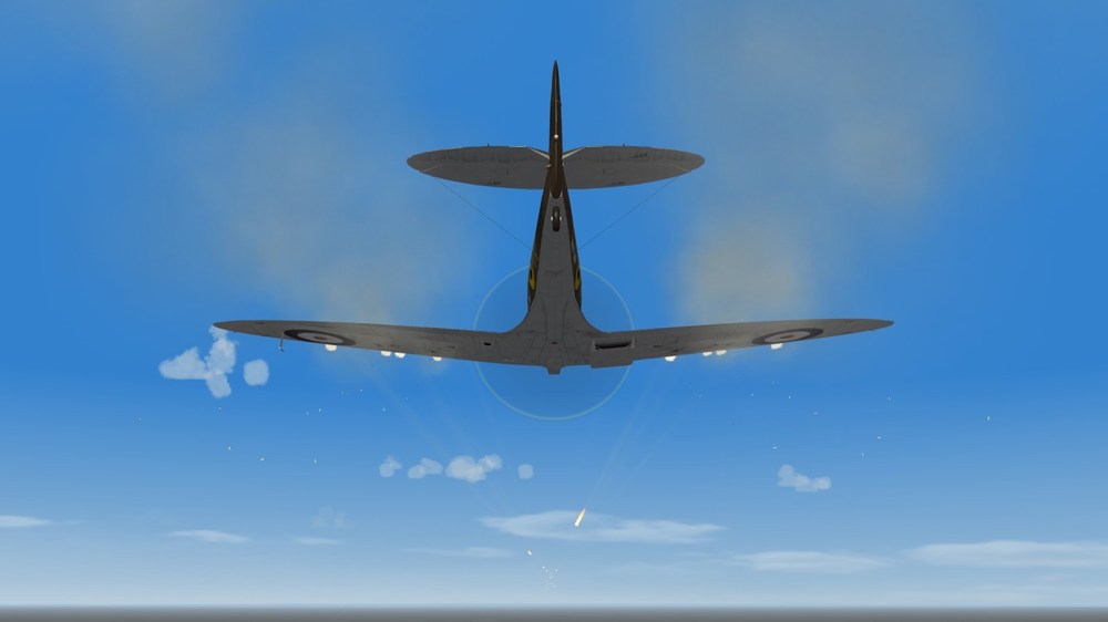
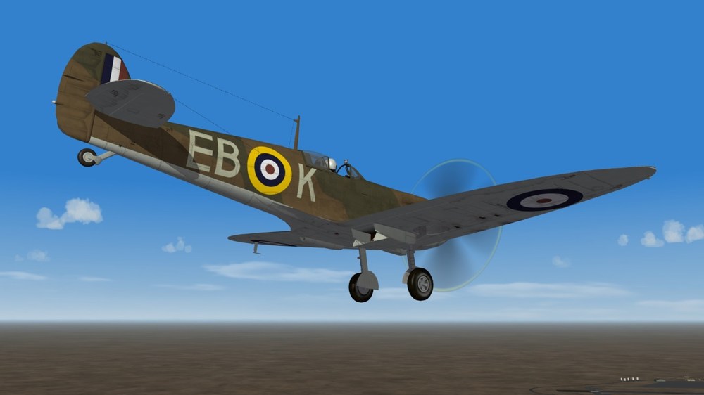
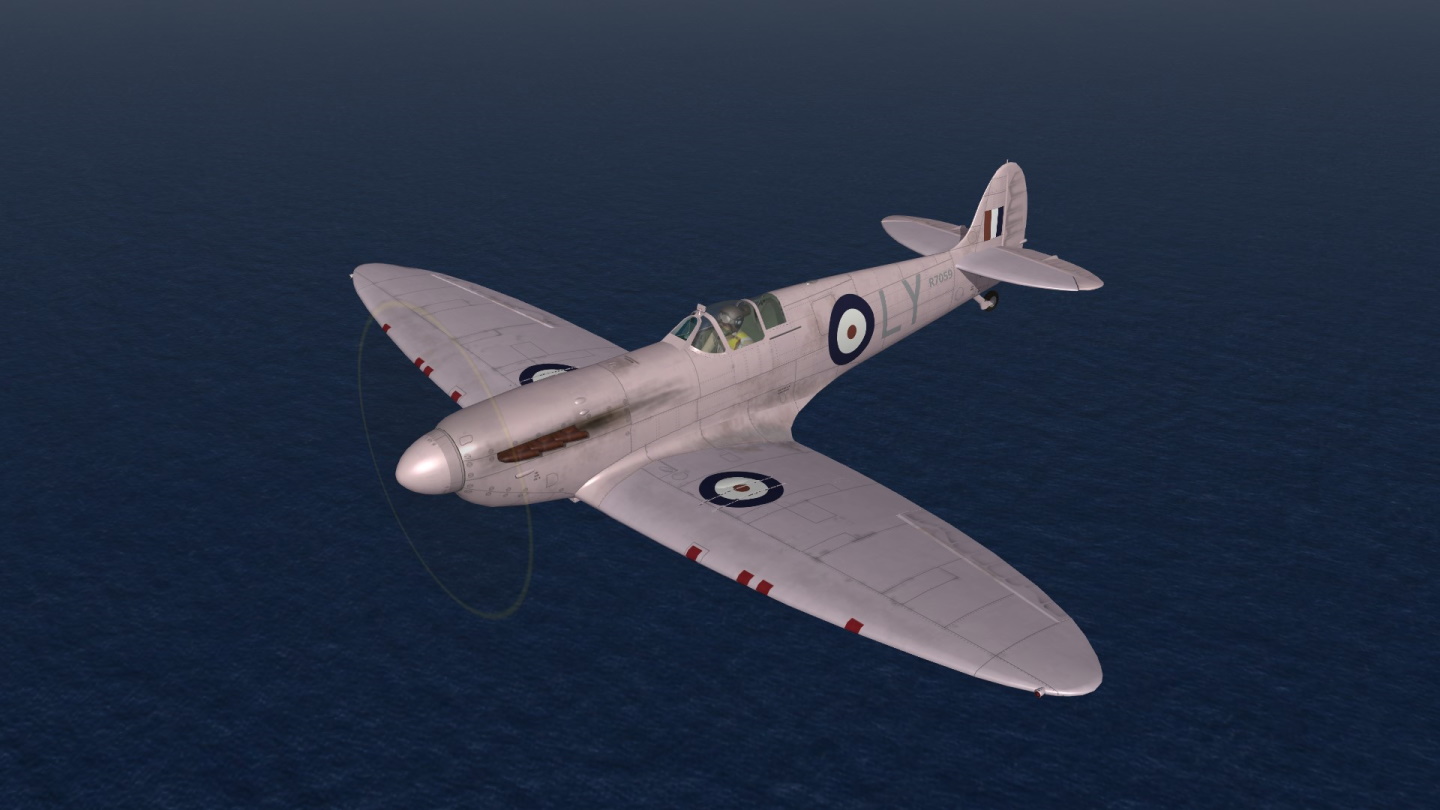
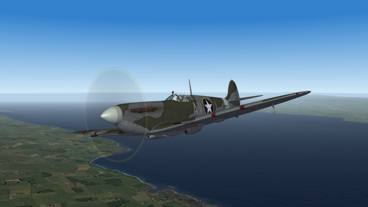
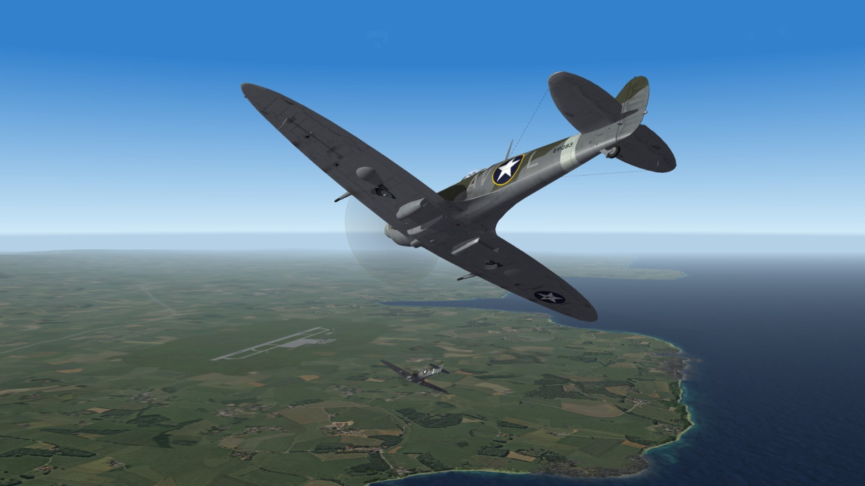
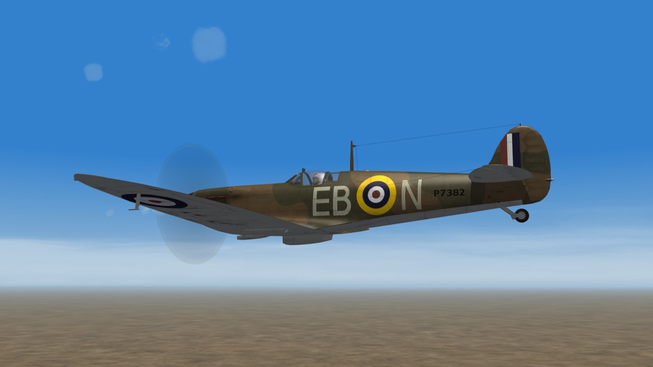
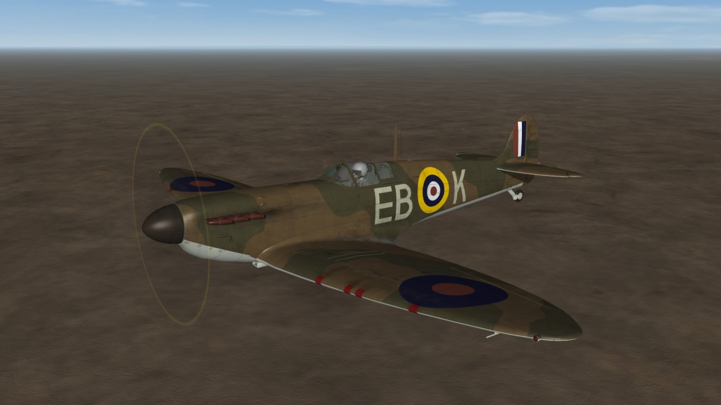
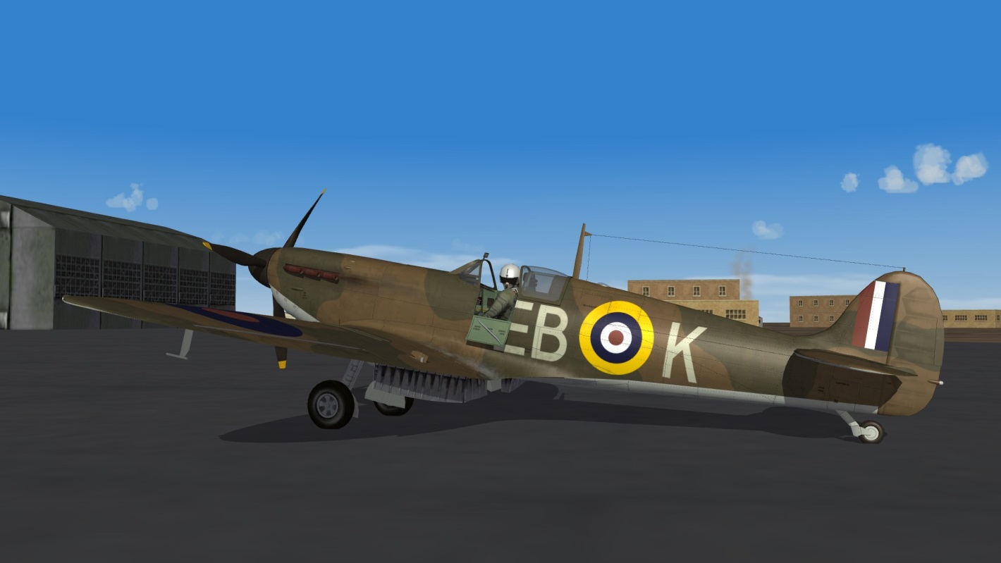
USAAF Spitfire MkVb


-
8
-
-
-
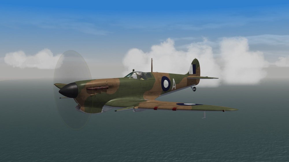
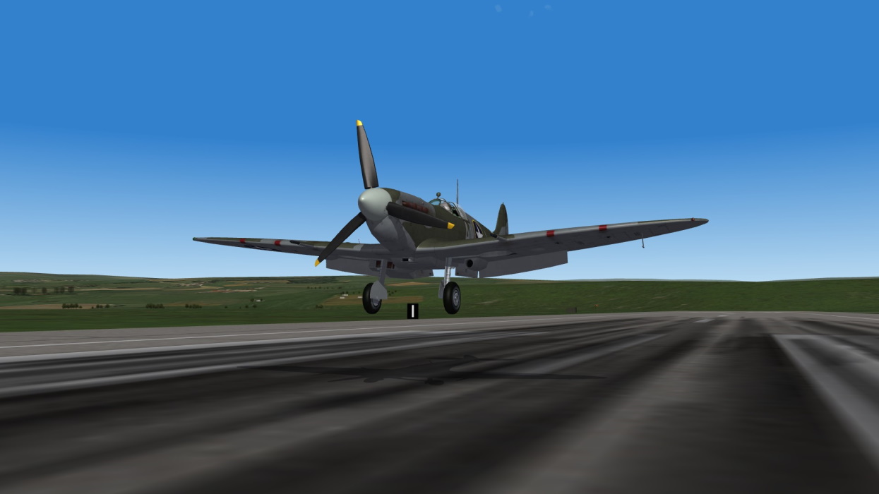
Tactical letters and serial numbers
-
12
-
-
2 hours ago, alexis99 said:F/A-18 and CF188 from here
Can you give a specific link in the download section for each of these aircrafts ?
Because I tried CF-188B and CF-18 and it was OK as it is.
I fully agree with all you wrote, just that I didn't found the issue you're pointing at. -
I don't know if this one is a reliable source :
But this one seems more authentic :
F-16 and T-38, not navy planes...
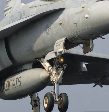
Navy plane :
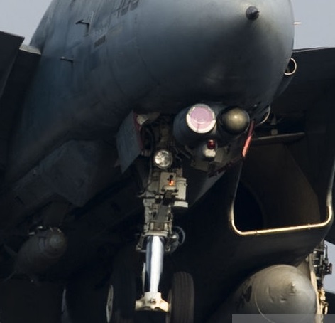
Another navy plane :
-
1
-
-
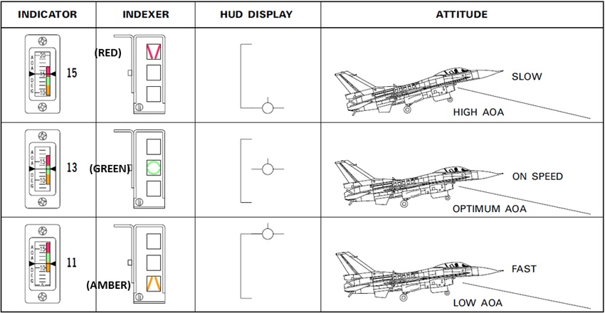
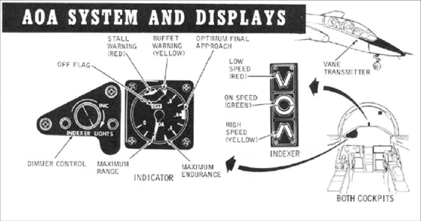
What you described "top light green too slow / middle light orange on speed / bottom light red too fast" is the US Navy system.
You should have that on all US Navy aircrafts, and all aircrafts build for the US Navy and used by foreign nations.But, in some case like the Mirage III, the colors don't have the same meaning because it's not an US Navy related aircraft.
And I don't know if it answers the question...
About the TItanic, I have the strong feeling that it was some kind of movie mistake, though I don't know the real operation of the helm of an Olympic class liner ship lol
It could be the exact move ^^ -
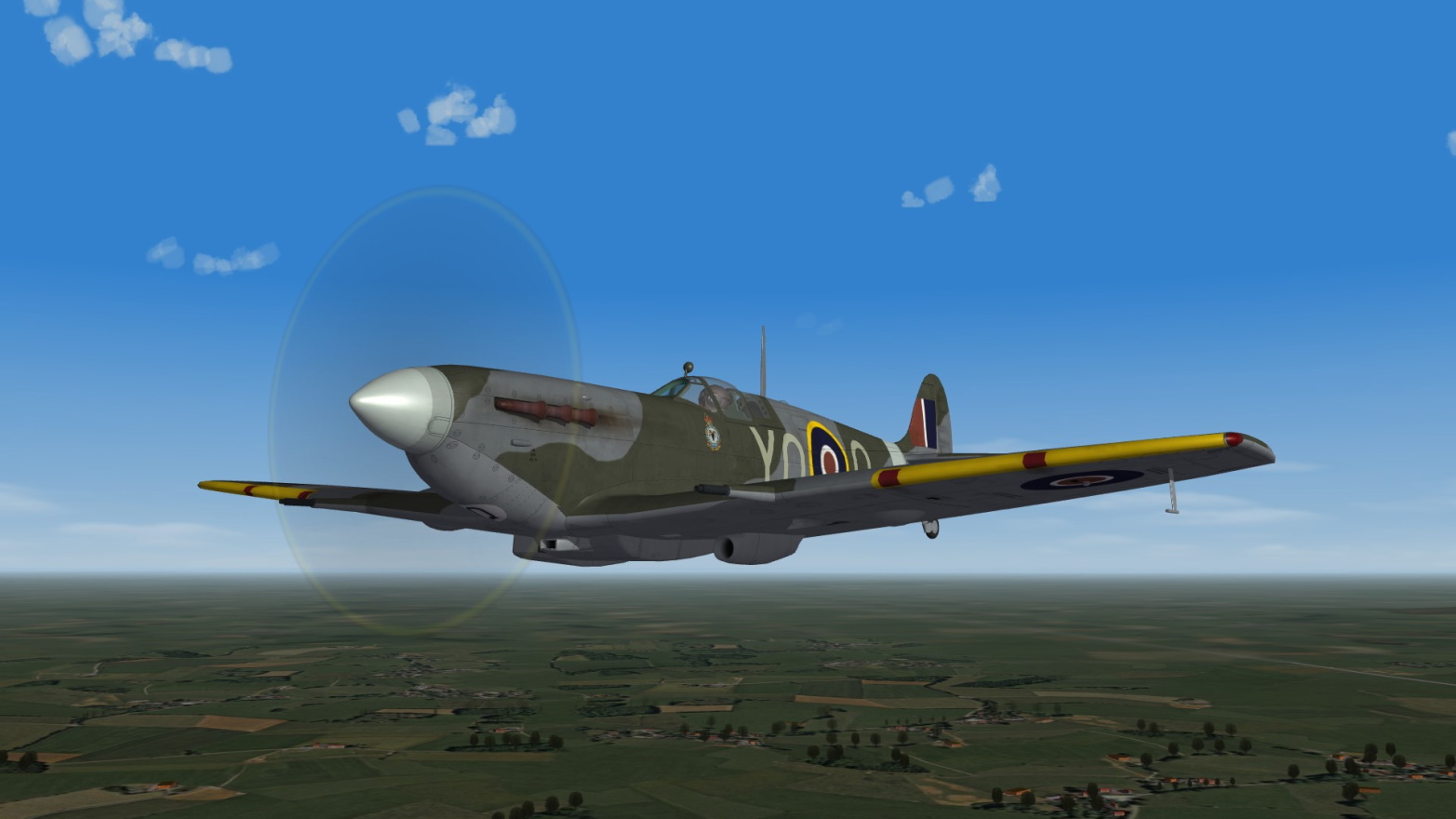
Thanks to Snapper21

Wrench
Logan
FM by ThirdWire
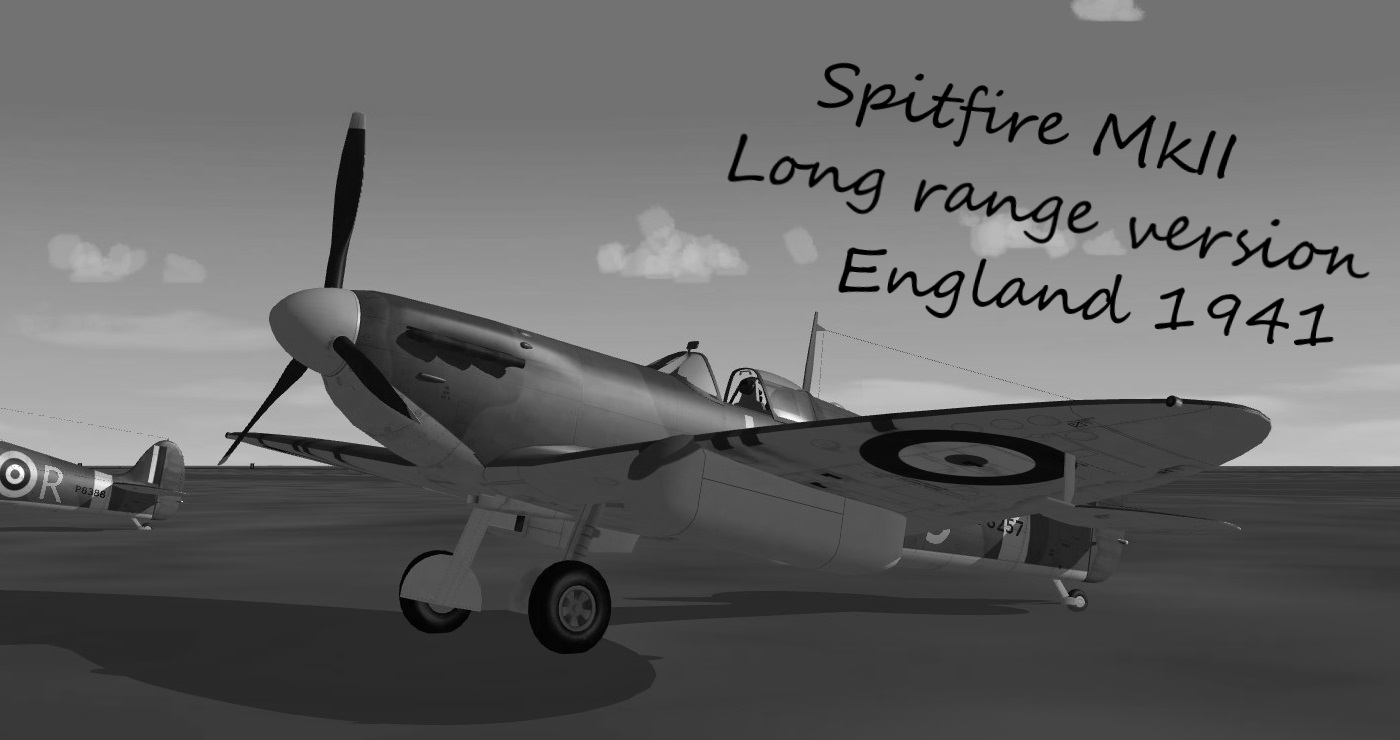
Spitfire MkIIa :


Still WIP but already very nice !
And I did almost nothing lol
-
6
-
-
May I jump in ?
5 hours ago, Wrench said:[Hide1]
ParentComponentName=Fuselage
ModelNodeName=
DestroyedNodeName=
DetachWhenDestroyed=false
HasAeroCoefficients=FALSEWhen using this kind of fake component to hide somthing from the model, or to make it visible from the cockpit view (which I do a lot),
please remember to allways add a "MassFraction=" value.
If you're hiding something then it should be "MassFraction=0.0"
If you want to show something from the cockpit and don't want to deal with the weight of the thing (like an antenna) "MassFraction=0.0" as well.
If you know how much the thing weights, you can add the "MassFraction=0.xxx" entry, as a fraction of the total weight.Why ? because most of the time, all components have a massfraction value except the fuselage that takes all the remaining of the weight.
So if the weight remaining for the fuselage is 500kg, the game will count 250kg for the fuselage and 250kg for the component added for display purpose (like a antenna...).Another way is to give a mass fraction value for all components, but then the total of all must be 1.0
My 2 cents, thanks for reading !
-
1
-
2
-
-
4 hours ago, Eagle114th said:4 hours ago, Eagle114th said:Cmq=-2.4830
CmqMachTableData=0.971,0.973,0.978,0.987,1.000,1.017,1.040,2.069,10.107,100.107,100.364,100.332,100.199
...is also a part of the effect of limiting the pitching response.
The Cmq has a negative value, it means this component will not ease the aero-interaction with the others components. It will counteract it.
And the coefficient goes from 1.040 to 100. That will block the pitching response.
But it doesn't really limit the elevator response, it acts on the FM ensemble. It's just that the elevators stay the same and cannot deal with such an increase of negative Cmq.Cmad value is similar but doesn't have "MachTable" scale.
-
1
-
-
That's what I had in mind.
Look at Logan's MiG-Ye8 for example, it has that tail-bumper :
[TailSkid]
SystemType=LANDING_GEAR
Retractable=FALSE
DragArea=0.0
IsSkid=TRUE
NoContactOnGround=TRUE
ContactPoint=0.0,-5.34,-0.7
MaxLoadFactor=0.5As long as there's a mesh in the 3D model, or at least a shape of it, there's no problem to add it to any aircraft, like the Canberra / B-57.
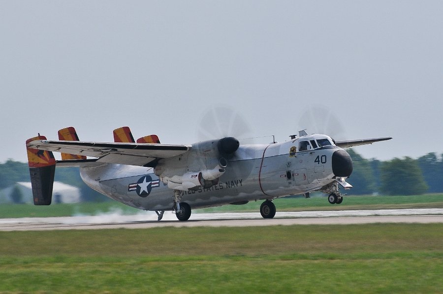
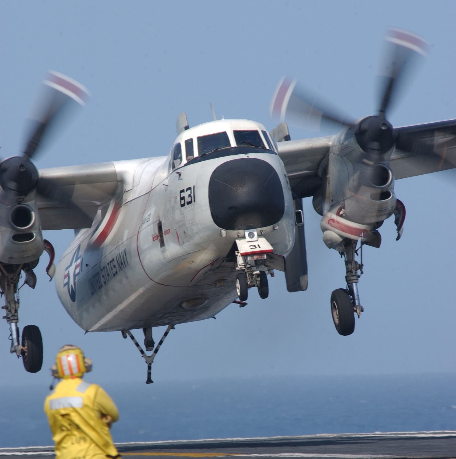
For the C-2, as it is an animated device, the shock/spring/damp entries should be used like Nyghtfall's example.
The important thing not to forget is "NoContactOnGround=TRUE", or the wingmen will pile up on the runway after landing.
-
1
-
1
-
-
The C-2 seems to have that tail-strike tendency, but it has a tail skid

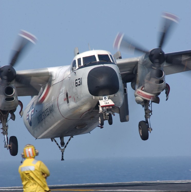
-
3
-
-
Here's what I would try :
First, in the 3D model, check that the "x=0,y=0,z=0" point is where the 3 axis should join.
- X in the middle of the aircraft
- Y just ahead of the main landing gear, between the nose and main wheels, but close to the center of the plane (around where it is actually on the aircraft)
- Z in the axis of the engines, just because it is simpler for the FM (it may not be not realistic compared to the actual plane)Then, check all the "MassFraction" values in the data.ini file.
Best is to have all components with a "MassFraction" value (even the fake components) and leave the Fuselage without the entry, and the fuselage component will take all the rest of the weight.
MassFraction value are 0.xx of the total weight.
Check the estimated weight of the fuselage.
If necessary create some component (like tail, aft section of the fuselage...)
Often there's no engine nacelles : create components for the nacelle to have drag and weight where it should be -> MinMaxPosition values should be checked tooI do that all the time.
Hope it'll help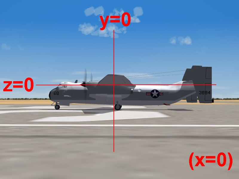
-
Yes it's degrees
What aircraft are you editing ?
-
-
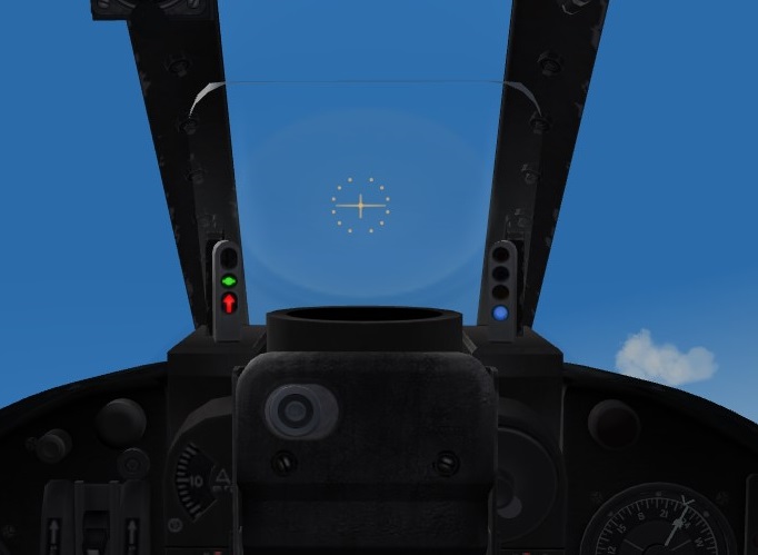
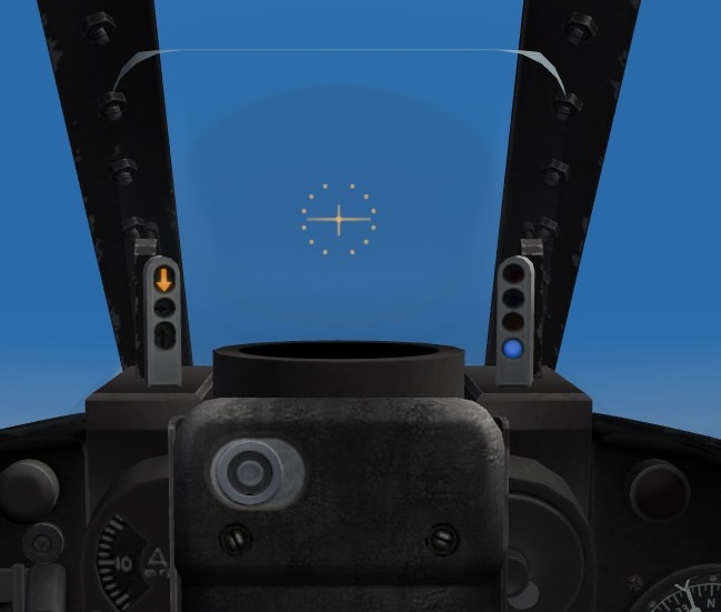
1 hour ago, alexis99 said:So how do you aircraft builders work out your AOA figures?
I'm not an aircraft builder, but I did some editing on the AOA lights in the cockpit ini file.
By testing, using the landing speed and the rate of descent -> the "on speed" light should work first.
Then defining margins I want for the "low" and "fast" lights, testing from other cockpit files values.Maybe the glide slope indicator could be useful for the "on speed" light value.
Or...
You could just testing by adding/substracting 1 degree for all values, and so on...
And testing - testing of course !


??? on Greek & Turkish TF-102s
in Thirdwire: Strike Fighters 2 Series - Mods & Skinning Discussion
Posted
As much as the single seater...