

Timmy
-
Content count
183 -
Joined
-
Last visited
Posts posted by Timmy
-
-
Lexx - check email.
Blackbird - that's a Yak-19. Lexx wanted one for his stargetic interceptor fleet so I'm trying to give him a carrot as I'm fresh out of sticks...
-
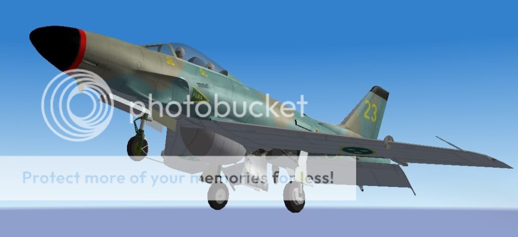
She's looking better on the ground. Thanks FC. Still twitchy - like she was being held just off the ground by a string attached at the cg, wobbling ever so slightly. It's wierd, I'm sure someone with actual experience will be able to correct it.
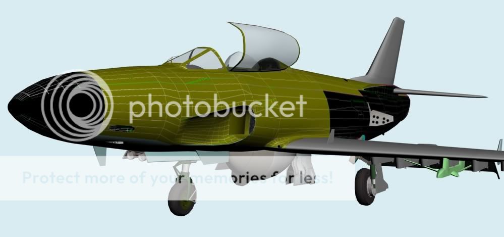
Lexx - Just as an incentive to you - here's the next thing in the pipeline.

-
It looks like that little Polish attack aircraft to me...
-
It really has no FM yet. I'm using the F-86D as a base for testing although I've done something to it that makes landings very tricky.
Speaking of landings. I've searched here and at TW and have yet to find a reasonable answer to this question... How do you get the gear to compress where you want it on the ground? I built the model using reasonably good drawings - so I'm happy with the relative size of the gear uncompressed. In real life, under the weight of the aircraft, the gear should compress much more than they currently do in the game. Is there a general rule of thumb to compress the landing gear under the weight of the aircraft on the ground or is it simply a matter of five hours tinkering with the spring and damping factors in the .ini file?
-
Skin still wip. But getting there.
-
I have an uncle who used to fly these in the Air Force. As I recall, he liked the aircraft because, "The engines usually waited until you were at altitude to quit - giving you enough time to find a place to crash."
-
I've got it sitting on the ground and not dancing/exploding. I'll send you what I have as soon as I get the mapping completed.
-
I'll have the re-mapping complete by Tuesday. Skinning continues. Lexx is in charge of the FM. He'll get to that when he gets to it. I'll probably release the model as a beta (without FM or good skin) by the end of the week unless RL decides to put the smack down on me.
-
I agree that mapping is the most difficult part of any 3d project.
So far I have little distortion. I understand the need to have panel lines running perpendicular but that need is compromised by the need to have everything as large as possible and for everything to look like the object you are trying to paint. As I stated earlier - I hate trying to paint the stock 3rd wire models because I can't figure out what anything is. IMHO, mapping swept wings as disjointed - straight panels butted up against each other makes no sense. I'd rather be able to see what I'm painting and sacrifice a bit of space rather than filling up every pixel with map.
This is what I now have (basically taking the 4 maps I already had and combining them.) This probably isn't as good as could possibly be done but I think scaling every major piece the same is important as well. Having wings with larger rivets than the fuselage looks goofy to me. I'll grant you that there is room for improvement here - but I doubt that I'll change it much from what you see. Thanks for the help!

-
So am I to understand from all of this that the majority would rather have one 2048x2048 map rather than 4-5 1024 or 512 k maps?
-
Awesome stuff there Geezer. I'm amazed at the speed some of you guys can crank stuff out. It takes me forever. Well done.
-
Look at the bitmap below. In the upper right corner is the left half of the vertical fin. I was planning on mapping the left half on the left wing bitmap and the right half on the right wing bitmap. The problem is that the game won't recognize multiple maps on the same mesh. So I've mapped myself into a corner. Just looking for a solution.

As you can see below - the vertical fin is mapped - but it shows up as a blue material in the game. (I have already solved the material problem with the fuselage that appears in this pic)

-
Ahh - the voice of doom...

I thought about the random damage factor. The only solution I can think of it to scale the vertical fin down and put it on one of the wing bitmaps. That won't cause major problems and the re-mapping won't be terribly difficult or tedious (no more than normal.)
I'm not too worried about the FM. Get to it when you get to it. I've still got some heavy lifting to do on this end.
-
Right now I have four bitmaps - Nose, Fuselage, Right Wing and Left Wing. The standard has been five (adding tail) so that's the way I've always done it - I don't mind multiple maps as long as I can figure out what is what. I really hate the TW default aircraft maps as they make no damn sense with parts everywhere. My opinion is to split the model up into top, bottom and sides so that it doesn't distort too badly - but leave it together so the skinner will know what is what.
The current maps are 2048X2048 and render beautifully in MAX. Not so much in the game - hmm, have to check out the detail levels...
Thanks for the answer. I'll get to testing.
-
Moving right along with the Lansen - I've tried to minimize the number of .bmp files while fillinf up as much space as I can. The problem lies in my mapping - I have mapped the vertical tail in halves on the left and right wing bitmap respectivly. Not knowing that there was a limitation in the game regarding multiple materials on a mesh (It renders fine in MAX but doesn't show in the game.) My idea for a work around is to split the vertical tail into two vertical tails while retaining the aerodynamic properties of only one tail. This will allow me to keep the current mapping - reducing textures - and allow for proper damage modeling by making the hit boxes the same on each mesh they should, in theory, be damaged eequally.
Like this:
VertTailLeft
ParentComponentName=Fuselage
ModelNodeName=VertTailLeft
DestroyedNodeName=DAM_VertTailLeft
ShowFromCockpit=TRUE
DetachWhenDestroyed=TRUE
DamageRating=DESTROYED
MassFraction=0.027
HasAeroCoefficients=TRUE
CD0=0.0007
Cyb=-0.3201
Cyp=0.0202
Cyr=0.2895
Clb=0.0031
Clp=-0.0002
Clr=-0.0028
Cnb=0.1447
Cnp=-0.0091
Cnr=-0.9511
CD0MachTableNumData=4
CD0MachTableDeltaX=0.469300
CD0MachTableStartX=0.00
CD0MachTableData=1.876000,0.999480,0.996480,13.299700
ClbAlphaTableNumData=15
ClbAlphaTableDeltaX=4.00
ClbAlphaTableStartX=-28.00
ClbAlphaTableData=-23.562,-20.743,-17.822,-108.739,-72.182,-8.599,-5.421,-2.216,1.000,4.211,7.401,10.555,13.658,16.694,19.649
ClpAlphaTableNumData=15
ClpAlphaTableDeltaX=4.00
ClpAlphaTableStartX=-28.00
ClpAlphaTableData=156.409,119.508,86.496,58.047,34.743,17.070,5.402,0.000,1.000,8.415,22.134,41.920,67.422,98.173,133.606
ClrAlphaTableNumData=15
ClrAlphaTableDeltaX=4.00
ClrAlphaTableStartX=-28.00
ClrAlphaTableData=-20.253,-18.526,-16.439,-14.032,-11.351,-8.450,-5.384,-2.214,1.000,4.194,7.307,10.277,13.047,15.564,17.777
CnbAlphaTableNumData=15
CnbAlphaTableDeltaX=4.00
CnbAlphaTableStartX=-28.00
CnbAlphaTableData=0.860,0.893,0.922,0.947,0.967,0.983,0.993,0.999,1.000,0.996,0.987,0.974,0.955,0.932,0.905
CnpAlphaTableNumData=15
CnpAlphaTableDeltaX=4.00
CnpAlphaTableStartX=-28.00
CnpAlphaTableData=-5.706,-5.146,-4.477,-3.711,-2.864,-1.951,-0.990,0.000,1.000,1.991,2.952,3.867,4.716,5.482,6.152
CnrAlphaTableNumData=15
CnrAlphaTableDeltaX=4.00
CnrAlphaTableStartX=-28.00
CnrAlphaTableData=0.102,0.110,0.117,0.123,0.429,0.710,0.913,1.038,1.000,0.884,0.604,0.130,0.126,0.120,0.113
MinExtentPosition=-0.06,-8.07,0.57
MaxExtentPosition= 0.06,-3.27,2.77
CollisionPoint 001=0.00,-2.543,0.78
CollisionPoint 002]=0.00,-4.952,2.709
CollisionPoint 003]=0.00,-5.092,0.708
SystemName 001]=Rudder
SystemName 002]=RedTailLight
SystemName 003]=TailLight
HasArmor=TRUE
ArmorMaterial=ALUMINUM
Armor FRONT].Thickness=7
Armor REAR].Thickness=7
Armor RIGHT].Thickness=7
Armor LEFT].Thickness=7
Armor TOP].Thickness=7
Armor BOTTOM].Thickness=7
VertTailRight
ParentComponentName=Fuselage
ModelNodeName=VertTailRight
DestroyedNodeName=DAM_VertTailRight
ShowFromCockpit=TRUE
DetachWhenDestroyed=TRUE
DamageRating=DESTROYED
HasAeroCoefficients=FALSE
MinExtentPosition=-0.06,-8.07,0.57
MaxExtentPosition= 0.06,-3.27,2.77
CollisionPoint 001]=0.00,-2.543,0.78
CollisionPoint 002]=0.00,-4.952,2.709
CollisionPoint 003]=0.00,-5.092,0.708
HasArmor=TRUE
ArmorMaterial=ALUMINUM
Armor FRONT].Thickness=7
Armor REAR].Thickness=7
Armor RIGHT].Thickness=7
Armor LEFT].Thickness=7
Armor TOP].Thickness=7
Armor BOTTOM].Thickness=7
Question: Will this work the way I want or should I re-map the vertical tail, rudder, stabilizers and ailerons into their own bitmap? The latter causing problems with space utilization within the bitmap (There will be gobs of free space on the tail bitmap if I keep everything to scale. Not being lazy - as I've yet to map the right side, but trying to be efficient (that's what I keep telling myself.)
TD
-
Let me tell you a secret kids, mapping an aircraft sucks ass.
It's not the mapping that's difficult. It's the mapping that will make for good skins that sucks. Each and every polygon has to be placed on a flat surface in such a way that when you put color on it - the rivets won't distort - and the decals don't bleed all over the train...
GUEST #4:
No, the food was excellent.
MAÎTRE D:
Perhaps you're not... happy with the service?
GUEST #4:
No, no. No complaints.
GUEST #4'S WIFE:
It's just that we have to go. I'm having rather a heavy period.
GUEST #3:
Hmm.
GUEST #3'S WIFE:
Mm mm.
GUEST #4:
And... we... have... a... train to catch.
MAÎTRE D:
Ah.
GUEST #4'S WIFE:
Oh. Yes. Yes, of course. We have a train to catch, and I don't want to start bleeding all over the seats. Ha, hm hm hm.
MAÎTRE D:
Madam?
GUEST #4:
Perhaps we should be going.
GUEST #4'S WIFE:
Oh.
MAÎTRE D:
Oh! Very well, monsieur. Thank you so much. So nice to see you, and I hope very much we will see you again very soon. Au revoir, monsieur.
-
Didn't know there had been one built. It's not a competition - I don't care which one you use - just as long as we have one to use!
-
I've got the lod and a skin (kind of) for the Swedish Rb-04 anti-ship missile if you are interested in adding it. I was planning on releasing it with the Lansen model but it would be easier for it to be included in a general wep pack. The Viggen used that missile also.
-
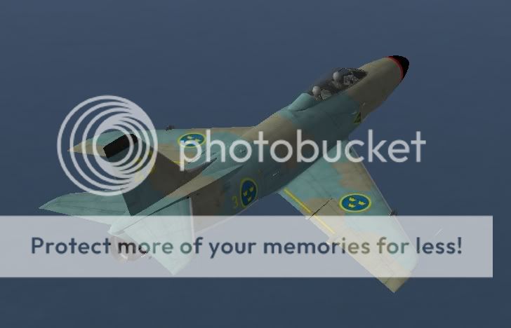
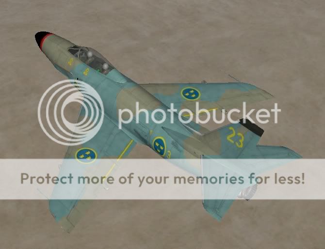
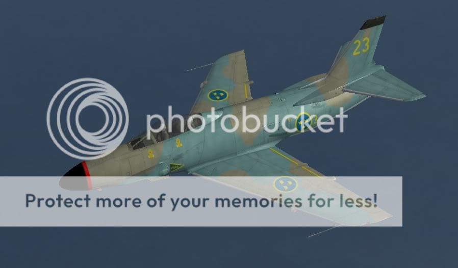
In yet more self promotion - here's where I am with mapping and skinning the J-32A.
-
-
Or the other way around - full compression on frame 11 and extended on 20 - as that's the state of the model on frame 11...
I'm only marginally this stupid - but an answer that I can actually wrap my brain around will save me enough time to make the windshield wiper animate.
-
FC
Not trying to be dense but do you use 11-20 to animate from the extended position?
Full extension on frame 11 and full compression on frame 20 with the gear extended?
Obviously I haven't tried that yet - too much bouncing plane syndrome as of yet. (My main gear wheels are out of round and have to be re-made.)
-
In TK's many descriptions of the gear animating sequences he always states the following:
At frame 0 the gear should be fully retracted and uncompressed.
It should start this way in key frame 1 (or 11 or whatever) and end in frame 10 with the gear extended and compressed.
Is this all that needs to be done for shock stroke in max?
I see a couple of paragraphs that explain that shock animation can de done seperatly. Could this be done with key frame 41 extended, uncompressed and frame 50 extended and compressed? Or is it in the same frames as retraction?
I'm having problems with the shock animation because of the canted stance of the main landing gear - simple linear motion throws the oleo out of the pison so I was thinking about animating the shock stroke. I'll probably be able to answer my own question with trial and error - but any input would be appreciated.
TD
-
I generally take an aircraft that is similar in size or shape (no help there) and change the .ini files to match my model.
For instance - I used the F-86K with the Lansen model. I renamed all the meshes and changed the positions of the pilots - afterburner - guns - the radius of the wheels. That will get it into the game. Then you will have to fix the rotation angles of the ailerons, elevators, flaps, rudders etc... Truth be told, I know nothing about getting the aircraft to perform properly, but I can get it into the game.
There is a program out there by p10ppy called min-max that will give you a great deal of information that you'll need regarding your model to get it working properly in the game. This program is invaluable and p10ppy was not only nominated for a Nobel Prize for his efforts, but was also cannonized by the Order Eels Keen on Hovercraft.
You can find min-max here: http://forum.combatace.com/index.php?autoc...p;showfile=5125
Lansen Update
in Thirdwire: Strike Fighters 1 Series - Mods/Skinning Discussion
Posted
OK. I just sent you what I have in my WOI folder. It's working fine here so I hope those files will get you up and running.