baffmeister
-
Posts
1,290 -
Joined
-
Last visited
-
Days Won
11
Content Type
Profiles
Forums
Gallery
Downloads
Store
Everything posted by baffmeister
-
SF2 Atlas Impala Mk.II by Marcfighters V2
baffmeister replied to Wrench's topic in File Announcements
After trying a few more things it seems the issue is very similar to one I had with the Hawker Typhoon. The Typhoon also had some issues with bounding box differences between the left and right sides. With the Typhoon, the wing heaviness varied when using racks to carry bombs or not using racks. I have absolutely no idea how this happens but it is a model issue and there is a "quick fix" for the Impala. Just disable all six racks like so and the issue is much improved: [LeftWingStation01] SystemType=WEAPON_STATION StationID=1 StationGroupID=1 StationType=EXTERNAL AttachmentPosition=-2.40,-0.52,-0.24 AttachmentAngles=0.0,0.0,0.0 LoadLimit=800 AllowedWeaponClass=BOMB,RP,GP AttachmentType=USAF,NATO,UK,FRANCE ModelNodeName=//LeftWingPylon2...................................................DO THIS FOR ALL SIX RACKS PylonMass=25 PylonDragArea=0.03 After the edit the wing heaviness almost totally disappears. I still notice some slight right wing heaviness on departure but it goes away as the speed increases. With the rack edit, the racks are part of the model and will always be visible. I've been doing some flight model edits to this plane over the last 5 days or so and have made some adjustments to the rudder behavior. Also, I found an online flight manual for the Australian MK-1 version so have adjusted fuel weights as well as gear and flap speeds, among other things. Might have a beta test FM ready in a week or so. -
SF2 Atlas Impala Mk.II by Marcfighters V2
baffmeister replied to Wrench's topic in File Announcements
Thanks for the vote of confidence but nothing has worked so far. Some discrepancies noticeable in the bounding boxes when using Mue's lod viewer. The Left vs Right wing racks have some differences that may be an indication of the "offset" model center. From past experience I know it doesn't take much of a difference in weight or distance of external stores to cause a noticeable wing heaviness. In this case the position of the external stores and the rack weights are all symmetrical in the aircraft data.ini so it may be a case of making the weapon positions slightly unsymmetrical to accommodate the model issue. The model error seems to be very small, only about 2-3cm but it's enough to notice. -
SF2 Atlas Impala Mk.II by Marcfighters V2
baffmeister replied to Wrench's topic in File Announcements
Jeanba, is the issue more noticeable when carrying external stores? I've been testing it out and think there may be a model issue, probably an offset center point on the model. -
The building objects you made for the Battle of the Bulge terrain looked good to my eye. I did run them through the lod viewer and didn't see any issues. Some 63% sized objects got used for other purposes, I think an old hangar used as a shed or whatever. I will package those objects eventually.
-
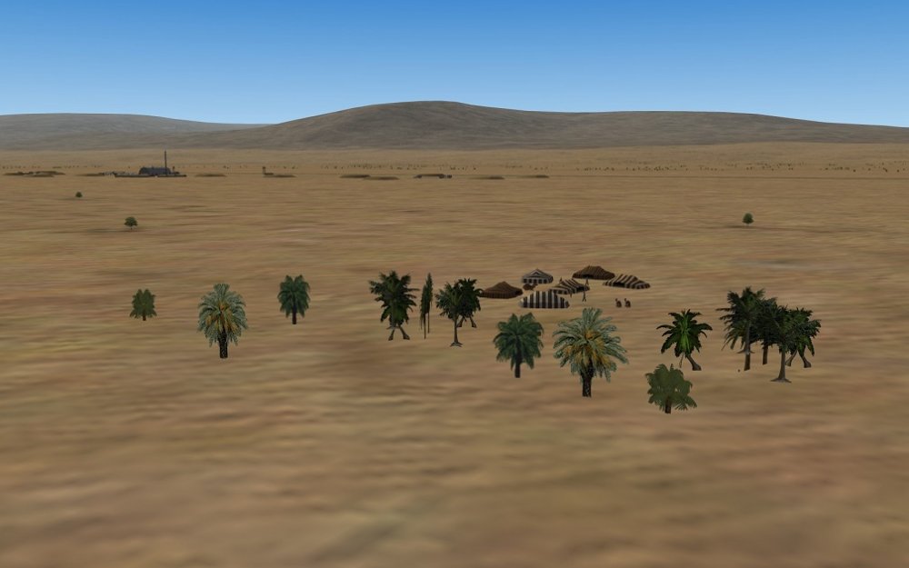
That's the whole idea, I think. They aren't used to make forests but just to add some additional visual interest to certain target areas.
-
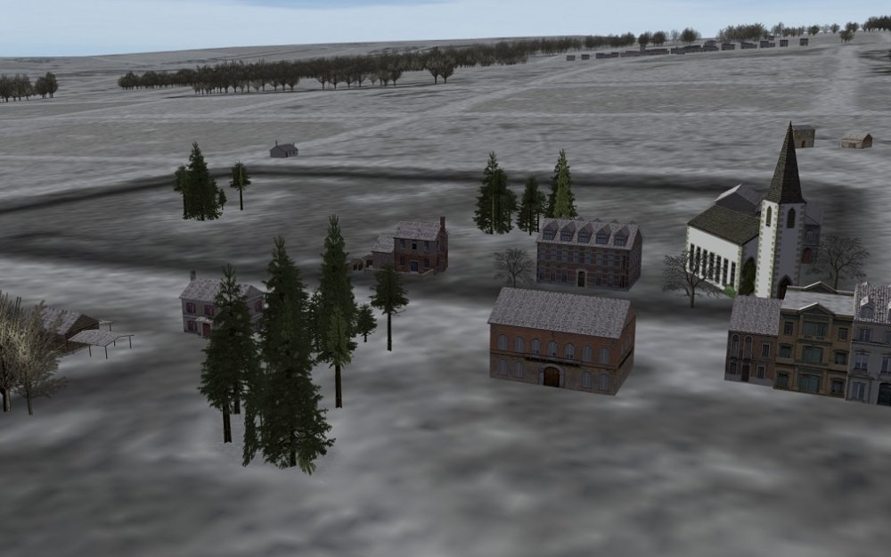
There are some tree models available but they aren't always easy to find. No formal "tree objects" have been uploaded, to the best of my knowledge. Here are some I found included with some terrains. Fir tree groupings found on Rends Germany terrain, and probably others. I re-colored the base for winter use and used it in the Battle of the Bulge terrain: Here are some palm trees that may use the same lod as the fir trees but with a different tga: Both those screen shots show 3 individual tree objects as well. Not sure where I got them but they are flat objects so to get a 3d look you have to place them in an X pattern. I think having some tree objects, both individual and in groups is a good idea. I don't know anything about model building but it might be possible to make tree objects with different tga's that would match different climates, giving the terrain builder a choice of various tree types.
-
I just did a similar test to what Mue did but using the stock ThirdWire SE-5 aircraft. My not very exact measurement using the lod viewer cursor gave a wingspan of 7.8 meters for the SE-5 model compared to a wingspan of 8.11 meters from Wikipedia. That's very close so I wonder, if the tank and the plane are more or less the correct size, then what objects are at 63%?
-
For an interesting look at one way the AI cheats, use hud de-bug mode, do an autopilot take-off with your plane, and watch the aircraft weight as it mysteriously decreases during the take-off roll.
-
Most of those objects can be found in the Battle of the Bulge terrain I put together. It's available here: https://combatace.com/files/file/16575-sf2-ww2-battle-of-the-bulge-terrain/ Now that you mention it, I should compile all of Geezer's SF-2 sized "Bulge Objects" in one package, with both winter and summer textures. Some day......
-
Interesting idea. They would require quite level terrain to look right. It might be possible to make the "zero point" above the actual base of the model so the model sinks into the ground a bit. I think that's been done before for some FE buildings so they sink into the ground a bit, for use on slopes.
-
In the shop for a double delta tune-up.
-
In SF-2, the wall is hard coded to 80km from the map edge.
- 7 replies
-
- 1
-

-
- early floggers
- flight models
- (and 5 more)
-
I would be surprised, but could probably be tested. [I'm too busy]
-
To further complicate matters, most of the older flight manuals mention the hazards of "rolling G", which can substantially reduce the safety factor when pulling high G's, I assume due to additional wing stress from torsional forces. I doubt the game takes that into account. After mentioning the wing breakage on the TW F-16 I was wondering, with all the computers on board, does the F-16 have an automatic G limiting system? If so it might be possible to model that but would require lot's of trial and error adjusting the max control speeds and mach tables for the H-stabs.
-
It's not that easy to break some airplanes, a lot depends on how much "available G" they have. ThirdWires F-16 is the only one I've broken recently, just for fun. At low level the available G is huge in the transonic zone so becomes breakable if you just yank back on the stick at high speed. Someone will correct me but I think, in general, the break point is about twice the rated G so a plane rated at 7G's might not actually break up until about 14G. Some structural damage/deformation might happen prior to the break point, and it could be enough to write off the airplane. I remember reading somewhere about a Mirage F-1 accidentally pulling something like 15-17G's and still landing safely, although the airframe was a write off. Also, I think some of the ThirdWire FM's, and my own, for that matter, are unbreakable because the available G is less than the actual plane may be capable of. That's to try and keep the pitch response from getting too sensitive at high speeds in my case, and maybe for TW FM's as well. I usually target a maximum of about 12 G's, which still gives the player the option of a "Hail Mary" high G turn.
-
It may have been made for the Canberra's but I think it's included with a few other planes as well.
-
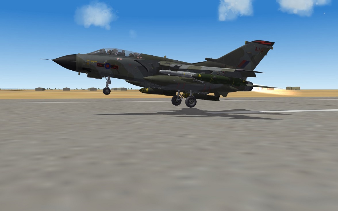
Tornado full flap "heavy mass" take-off.

-
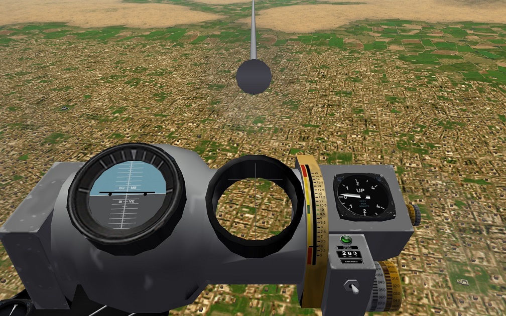
I was wondering about this bomb sight, which is available with some downloads: I haven't found any instructions yet. Stary's Yak-28B bomb sight looks interesting. Will check it out.

-
MiG-21Bis and Bis-B FM Mods
baffmeister replied to baffmeister's topic in Mods & Skinning Discussion
Thanks Gepard, at this point I'm not sure how to best implement the MiG-21 flap system but will do some testing. -
Very difficult to find the problem without more information but typos in the aircraft.ini or cockpit.ini are good places to check. You may want to check out this late model westernized MiG-21 which might be a better starting point for your project. https://combatace.com/files/file/11543-mig-21-lancer-a-c/
-
MiG-21Bis and Bis-B FM Mods
baffmeister replied to baffmeister's topic in Mods & Skinning Discussion
I spent some time trying to find more information on the MiG-21 flap arrangement but didn't find any solid information. I did find enough to agree with Gepard, the flap set up wasn't considered a combat flap. Described as a "Floating Flap" or "Swimming Flap" the maximum deployment angle depended on aircraft speed. For example, during approach to land you would select flap 25deg but if the speed was relatively high, the flap wouldn't deploy the full 25deg but some lower angle. As the speed decreased the flap would continue to deploy until at the "right" speed it would reach 25deg. I assume it would work in reverse as well. I didn't find any evidence that any of the later versions such as the LanceR or Bison received a dedicated combat flap but India did some wind tunnel testing with models in 1985, investigating the potential for combat flaps on the MiG-21. There is some anecdotal information suggesting the floating flap may have had some benefit during combat maneuvering but probably at quite low airspeed and possibly more for defensive maneuvers as the drag would be quite high from the "simple" flaps. I did watch a LanceR airshow video with the plane maneuvering and doing rolls with extended flaps but couldn't tell if the flaps were moving through a range of travel. At some point MiG-21's were equipped with a Boundary Layer Control system [AKA Blown Flap] that worked when the flaps were in the landing position. The early versions didn't have the BLC system and that seems to be reflected in the stock TW FM's, with the early F-13 having less flap lift than the later versions. I don't think the early versions had the floating flap set up either, so the two systems might have been implemented at the same time. I haven't found any solid info on the speed range for the floating flap but the present speed range is probably too high with possibly too much lift as well but will leave it "as is" until I get more information. I found more support for reduced main rack weights, in the 24-28KG range. Also, the MiG-21Bis did get a slightly enlarged air intake as well as some refinements to the ducting. It also received some structural refinements to increase strength while avoiding a significant weight increase. -
MiG-21Bis and Bis-B FM Mods
baffmeister replied to baffmeister's topic in Mods & Skinning Discussion
I will look into this closer but have seen a couple of online sources that seem to suggest a combat flap set up available on later versions. A manual combat flap set up might be a possibility as well, and maybe preferable, but would need more info on limit speeds. Your comments on the air intake are interesting and something I was wondering about. I'm just using a standard TW mach table for the "special regime" but thought it might not be the most realistic approach due to potential airflow limitations with the small intake. Finding good data regarding the thrust available over the mach/altitude range for the special regime would be very difficult, I think. -
MiG-21Bis and Bis-B FM Mods
baffmeister replied to baffmeister's topic in Mods & Skinning Discussion
Not familiar with those kinds of things, could you just make a late version? I took a close look at the thrust output from the stock engine data and it hits the fourth afterburner stage/full thrust at about 92% throttle. The emergency thrust kicks in at about 98-99% throttle so the present dead zone looks OK. If you target 94-96% throttle position you will get full standard thrust when desired, without engaging the emergency thrust. -
MiG-21Bis and Bis-B FM Mods
baffmeister replied to baffmeister's topic in Mods & Skinning Discussion
I wasn't aware of that one. Will look into it. -
I found some interesting MiG -21 data online so did a mini review of the ThirdWire flight model to see if there was any room to improve the performance a bit. Regarding the aerodynamics everything looked good and any changes that would have been made based on the data would have resulted in slightly worse performance so I left it as is. Best areas to improve performance were some adjustments to rack weights, some potential adjustments to empty weights on some versions but not the Bis, implementation of a combat flap set up for the later versions, and a work around for the Bis series to model the very large emergency thrust setting that was available below 4km/13123ft. There was a 3 minute limit on that system but it's not modeled. Might try something in the future to get an engine blow up at some point past 3 minutes but it's low priority. Here's some info on the changes: Engine Boost: I've been aware of this capability for a long time but didn't think it could be modeled. Turns out, it can! The engine afterburner mach tables use the same altitude table as the dry mach tables so what I did was add a second engine to the Mig-21Bis, but it supplies thrust in afterburner only. It adds additional thrust bringing the total thrust to 21825lbs static. At 13000ft the altitude table included with the second engine starts cutting down on the thrust until it's completely gone at 14000ft. The additional fuel consumption with the added thrust is modeled but it's not as bad as I suggested in a screen shot. After fixing a mistake the fuel lasts around 4 to 4 1/2 minutes but the fuel consumption and thrust can vary quite a bit depending on mach number and altitude. The additional thrust activates at about 98% throttle so to conserve fuel you will want to use the AB with discretion. It just occurred to me now I might be able to set the main engine up so it gets it's max thrust around 90-95% which would leave a bit of a dead zone between the main and second engine. Will give that a test at some point. Combat Flaps: This system appeared on the later versions, possibly first appearing on late production PFM's but not 100% sure about that. A graph showed the additional lift from the combat flaps that was available at speeds up to mach 0.90. I'm not sure how they worked in RL but these ones are just set to automatic mach and are fully deployed at 0.30 mach and fully retracted at 0.90mach with a continuous variation between points. The combat flap system worked between 0deg and 25deg flap angle. With the automatic combat flaps the landing flap setting is no longer available. Rack and empty weights: With the smallish low lift delta wing the MiG-21 suffers badly from increased weight. Any legitimate weight savings would help a lot. Anyway, from the info I was looking at the weight of the main racks was considerably lighter than the TW values so I made some adjustments. Aircraft empty weights need more research but the Bis looks about right and the MF looks too heavy by about 240kg. Any further information on these topics would be appreciated. Here are beta test FM's for the Bis and Bis-B: MiG-21BisFM's0.95.zip