Svetlin
-
Posts
919 -
Joined
-
Last visited
-
Days Won
4
Content Type
Profiles
Forums
Gallery
Downloads
Store
Everything posted by Svetlin
-
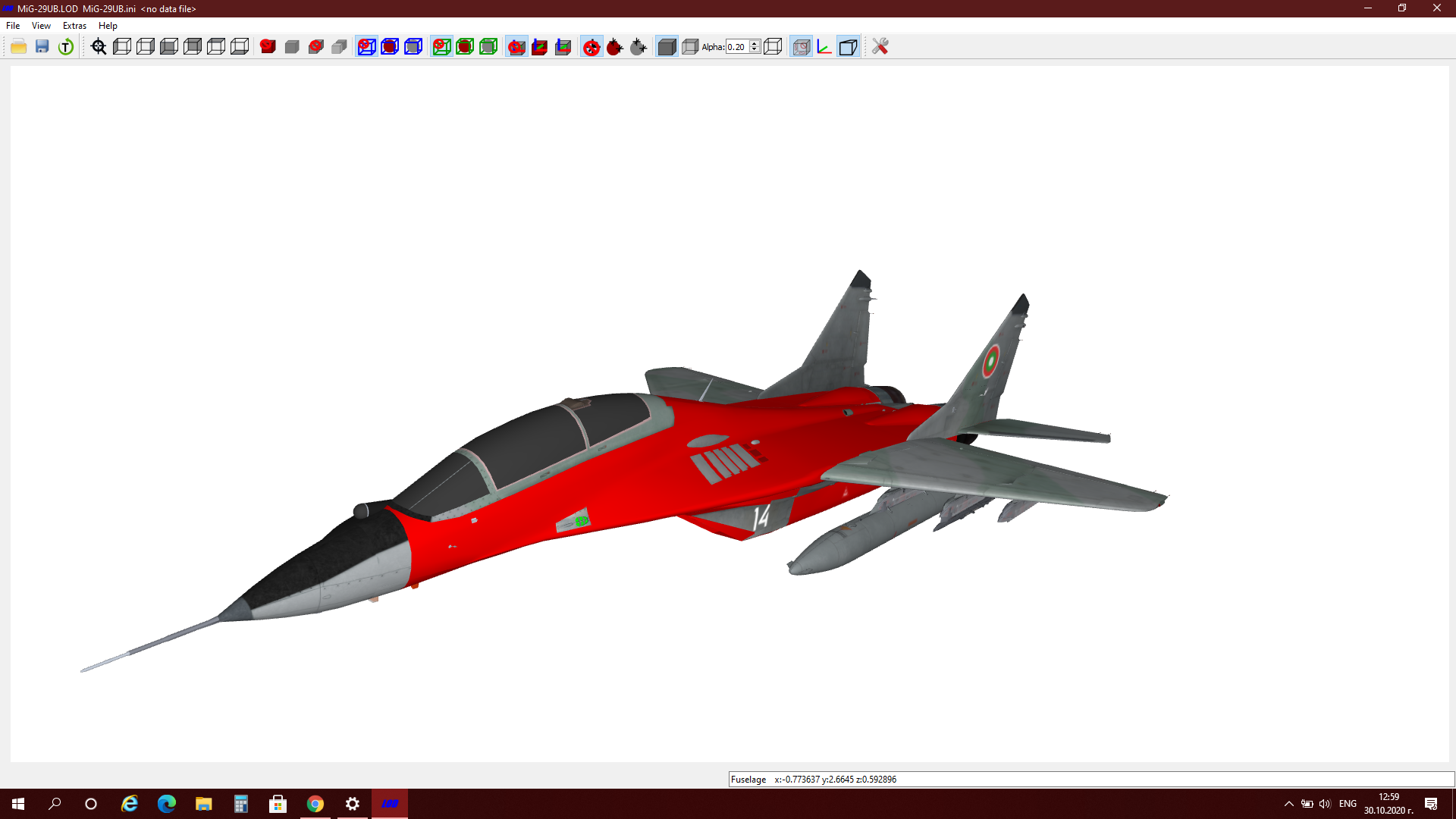
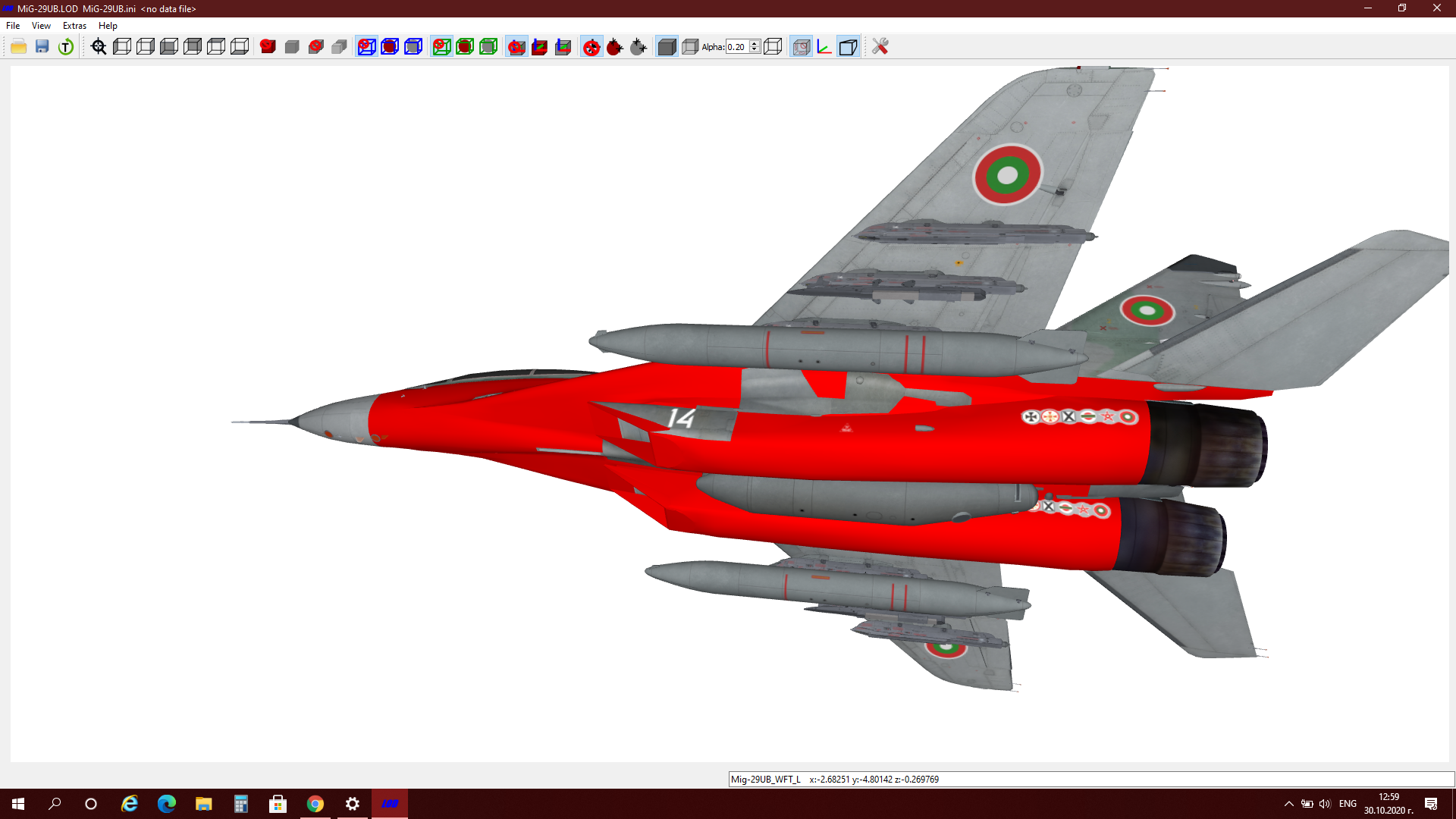
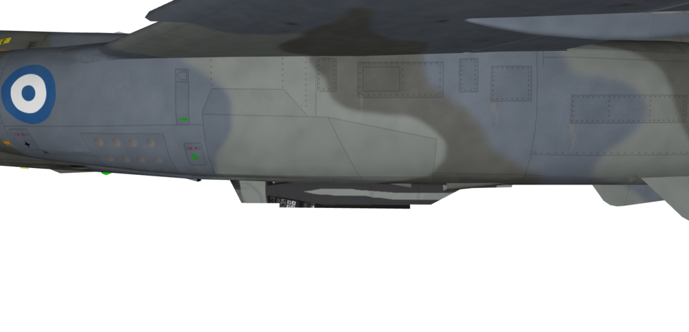
I think that partly the problem that Ngr faces is related to how the aircraft was modelled and split in different meshes. Here is what I mean: The decal just in front of the exhaust is supposed to be on the outer side only, but because the whole middle section of the aircraft and the 2 engines are a singe mesh, when you apply a decal that should face left, it appears both on the right engine and the left engine facing left. The same happens to a decal that is applied on the upper side of the fuselage, that should face top - it appears also inside the engine intake, facing top. I do not know of a cure to this other than cutting the section into more meshes, allowing independent placement of decals. In my case above the decal appearing at the wrong place is a minor problem. I had to reduce the size of the board number (14) on the intake, so it could fit entirely in the separate mesh, which I believe the model creator included especially for placing the board numbers and preventing them from appearing at wrong sides of the intakes. The problem though is that in reality the board number should be bigger, but still I would call this a minor problem. Aside from these issues though I am extremely happy with both the MiG-29UB and MiG-29A models as the level of detail is exquisite.


-
Thanks
-
Guys, if you plan to update this model to v2 as with other Mirage F1 models, may I ask you to fix the Aegean Ghost skin? The problem is with the centerline R-530 pylon:
-
https://www.britmodeller.com/forums/index.php?/topic/234993173-is-this-a-british-or-european-dual-bomb-adapter/ http://www.mlaviationwhitewaltham.yolasite.com/things-we-manufactured.php
-
I would say they had to do it that way for better/easier steering while taxing. It is called positive wheel/tyre camber. Since the nose gear is angled so much forward, when you turn right for example, the left tyre would either entirely loose contact with the ground, or only a narrow part of its working surface would remain in contact. Respectively when you turn left, same thing would happen with the right tyre. The positive camber helps in that during a turn the inside wheel/tyre would actually deform, allowing a wider surface to be in contact with the ground and the outside wheel instead of being lifted from the ground or have very narrow touch with it, would actually have a normal width working surface touching the ground. In other words, the positive camber in this case means more grip for the nose wheels and hence better steering especially at higher speed.
-
Out of curiosity, what is wrong with the nose wheels, Wrench? These look correct to me on your screenshot above.
-
http://airwar.ru/enc/attack/g2.html http://wp.scn.ru/en/ww3/a/353/111/0 https://flyawaysimulation.com/downloads/files/23769/fsx-soko-galeb-update/ The last link is to a free model for FSX and I guess you could use the skins there as reference.
-
Check here: https://combatace.com/forums/topic/81120-matra-super-530-missile-info/?tab=comments#comment-653657
-
Congratulations, well deserved! His mods on the Mirage 3/V family are among my favorites in this sim.
-
PM sent
-
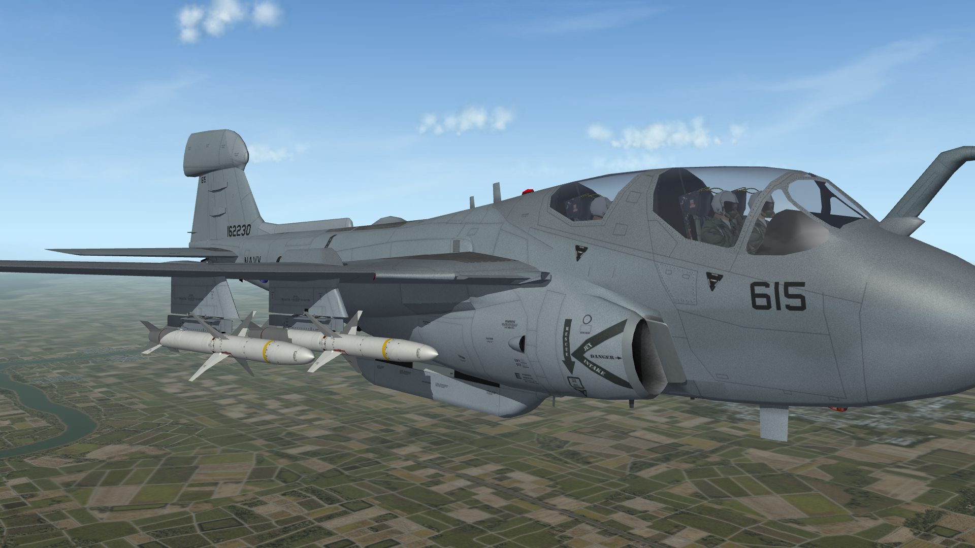
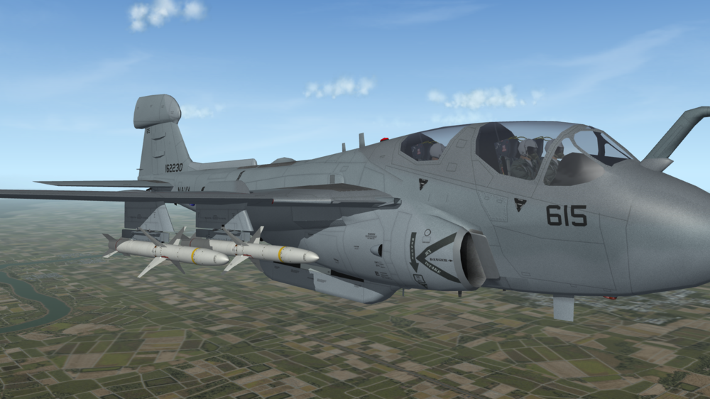
Thank you so much once again, ravenclaw! First goal achieved - the stock EA-6B can now carry AGM-88 on any one of the wing pylons and with a proper rail at that: Loaded with 4 AGM-88 just for the screenshot.
-
Spot on, ravenclaw, thanks a milliion!
-
Of course, thank you so much!
-
If it is not too much to ask, could I have a white one and also a light ghost grey painted one?
-
Ravenclaw, I would prefer to have a single launchrail model, so I could use it on different aircraft and also to represent asymmetrical weapons load. I will set it as an empty fuel tank, that cannot be jettisoned.
-
Hi ravenclaw, if it is not much trouble for you and it does not take too much time to make it a separate lauchnrail model, then I would greatly appreciate it.
-
Good day everyone, hope I find you all safe and in good health! Has anyone come across a separate model of the LAU-118 launcher adaptor for AGM-88 HARM in any of the weapon packs or in any mod?
-
Not in my install, KJakker. Are you sure you are looking at the stock MiG-23MLD? In my install the MiG-23MLD does not have engine nozzle animation.
-
No ejection seat as well.
-
As per Yefim Gordon:
-
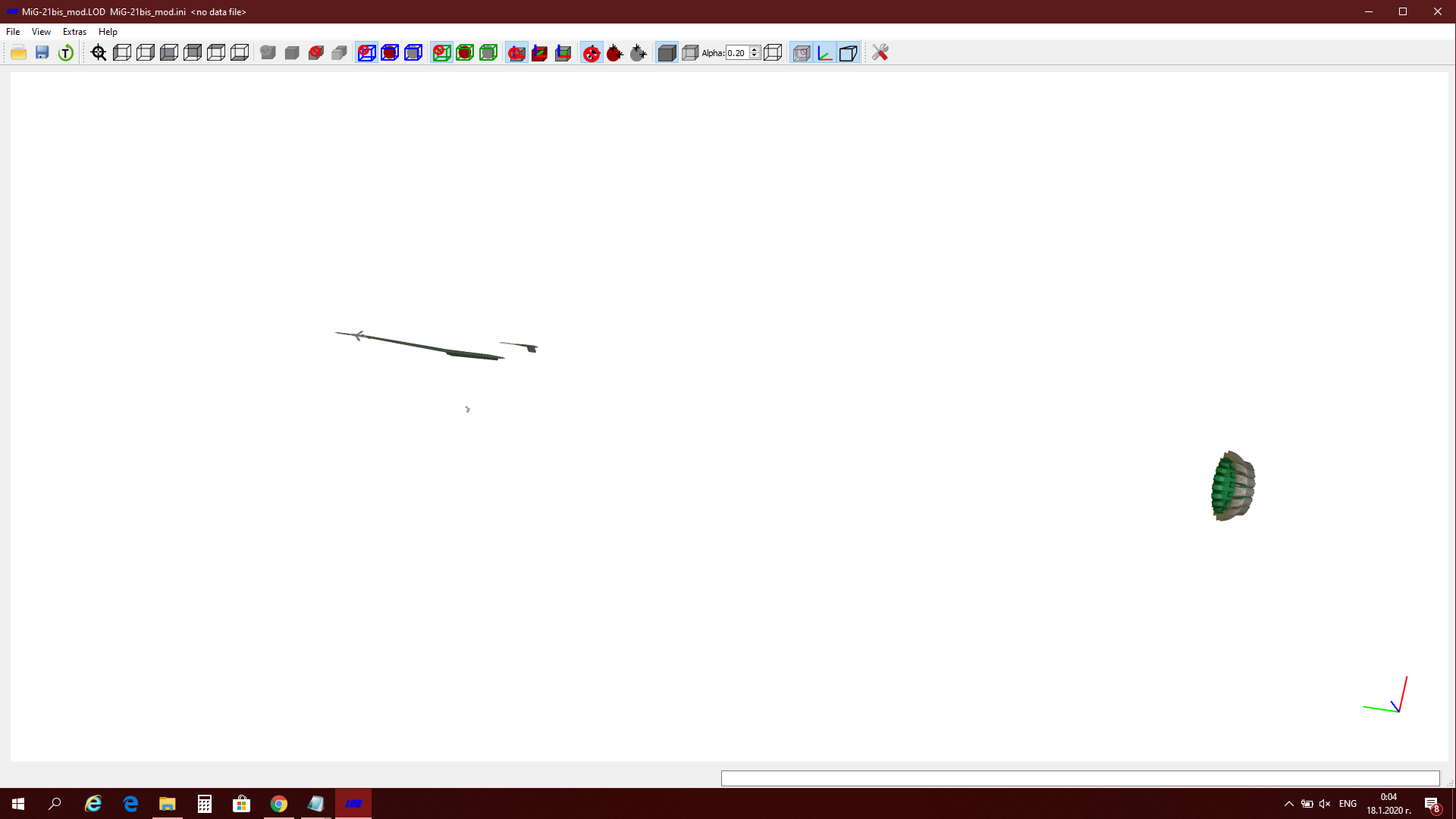
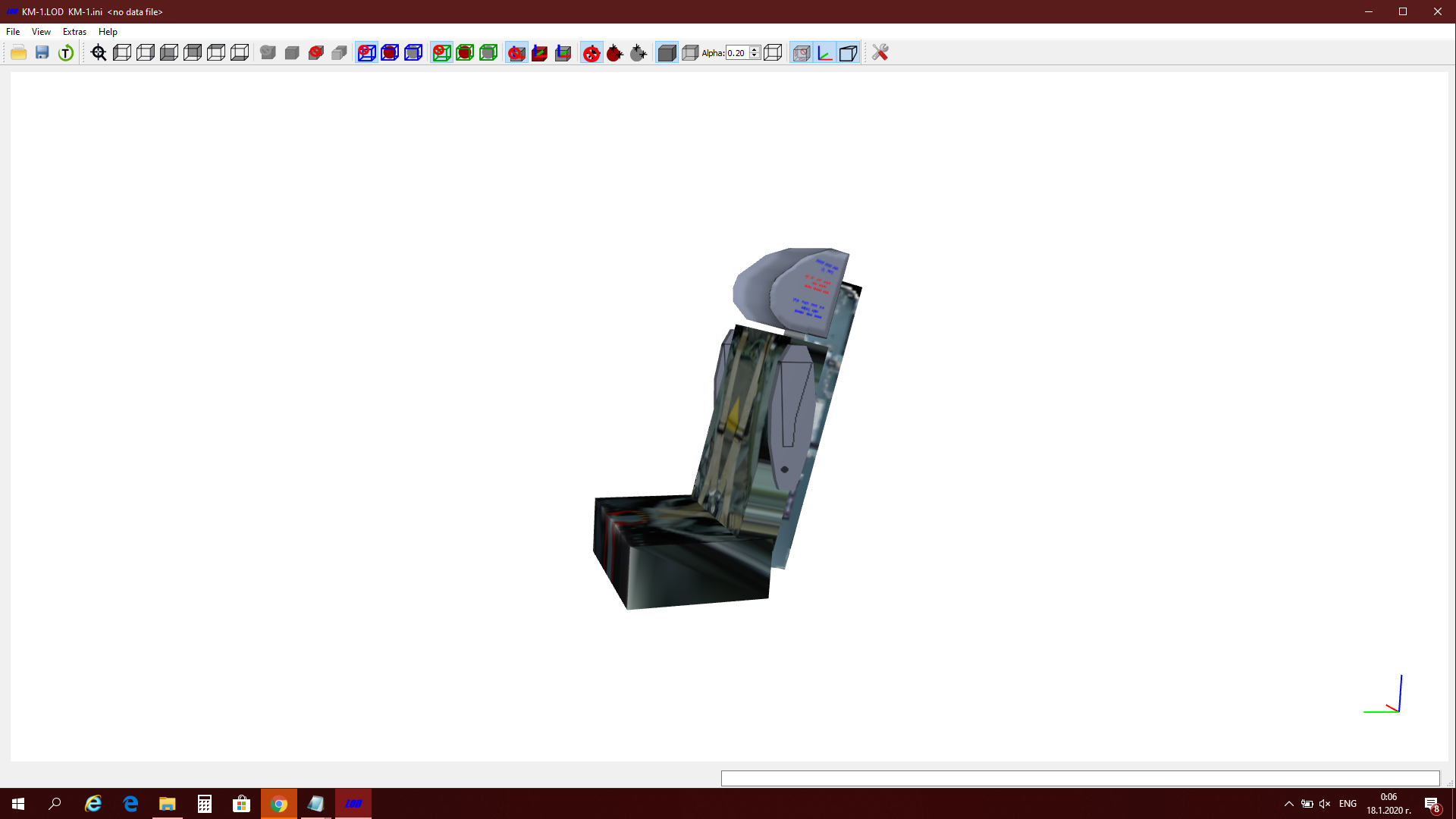
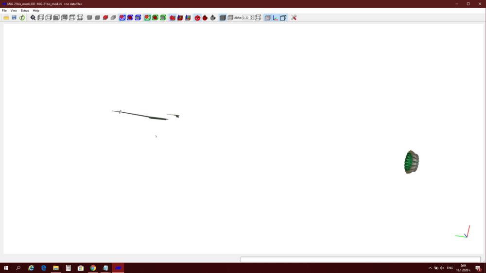
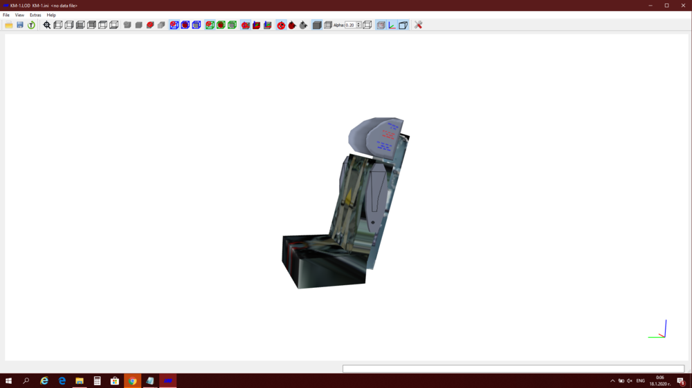
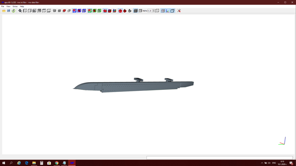
OK, so by slightly adjusting the ShockStroke and SpringFactor values for the nose gear I achieved a result that satisfies me. The aircraft has in my view a better stance than before. My current nose gear values are: ShockStroke=0.33 SpringFactor=0.6 The nose wheel sits well on the ground and during take off, the nose slowly gets raised, the shock gets slowly extended with the wheel staying on the ground until the shock is fully extended and only then the wheel leaves the ground. baffmeister, after checking your data.ini, I noticed room for some more visual improvements. The first one would be to add the correct ejection seat and we have the KM-1 seat from Florian's MiG-21UM mod (though the seat there is named KV-1, the correct designation of the ejection seat is KM-1 and KM-1M). The second one would be to add 3d parts created by Spillone104 and available here at CA, which consist of new pitot tube and engine detailing: The third one would be to make use of the APU-60-1 launch rail for R-60/AA-8 missile, which (if I remember well) Cocas was kind enough to build by my request: I have a Bulgarian MiG-21bis for personal use with the above improvements added. I am in the process of updating it with your data.ini, so eventually I will have your data.ini with my minor modifications to it to add the proper seat, Spillone104's details and Cocas's porper missile rail. I posted a screenshot of it on page 2 here with the missile rail added to the inner wing pylon. The proper stance in that screenshot was achieved by changing the CG position. Now with the help of the community I am happy to have that stance without negative effect to the FM.
-
Hi Cliff7600 and mue, thank you both. Fiddling with the gears entries seems less risky, as long as it does not lead to the aircraft exploding on the runway, so I will give it a try.
-
baffmeister, may I ask you a question? I am using this thread since it is somewhat MiG-21 related as well. I have not had the time to test the new data.ini you offered here, so I do not know, may be the issue I have in mind might have been addressed there. I am writing about the angle of attack the aircraft has on the ground (or the stance as I've heard it being called). The stock TW MiG-21 sits in a well visible nose-up position, while in real life pictures the aircraft seems horizontal or just slightly nose-down (I am not considering pictures of the aircraft on the runway before take off with the throttle up and brakes applied). Is there any way to control the stance of the aircraft on ground, without affecting the FM of the aircraft? I know out of personal (and rather ignorant I must admit) tests with the CG position entry in the aircraft data.ini file, that by changing the position of the CG, the stance of the aircraft on the ground changes. Changing the CG position does affect the FM though, so I doubt it is the right thing to do. I also know that each aircraft component in the data.ini file has an entry for the weight (for example weight of the nose, weight of the tail, weight of the wing, etc.) and I guess a rather low weight entry for the nose or a rather high one for the tail or other component aft of the CG may cause the aircraft to have a nose-up stance, but I have not messed with that yet. I believe I recall seeing somewhere an entry in the aircraft data.ini addressing just the angle of attack on the ground (it was something like aircraftongroundangle=) and I checked several stock TW aircraft, but could not find the correct entry. Any ideas?
-
The file was updated and now has to be approved again. Hopefully someone will do it soon.
-
Adding Weapons Pylons and Stations
Svetlin replied to ShrikeHawk's topic in Mods & Skinning Discussion
The fake pilot method works perfect for objects that need to stay permanently fixed on the aircraft. So one needs to consider if the subject pylon is to be constantly visible on the aircraft or not. In other words, if the fake pilot metod is used, then no matter what type of weapon is selected or if any weapon is loaded at all, the pylon will stay fixed on the aircraft.